When dealing with embedded systems, selecting between SPI vs I2C for communication between microcontrollers and peripheral devices can greatly affect performance, design complexity, and cost. This article provides a comprehensive analysis of SPI (Serial Peripheral Interface) and I2C (Inter-Integrated Circuit), the two primary serial communication protocols enabling efficient data exchange within these compact systems. Let’s delve deeper into this topic.
SPI (Serial Peripheral Interface)
- Architecture: SPI adheres to a master-slave architecture. A single master device orchestrates communication and synchronizes data transfer with one or more slave devices. This simplifies communication but restricts it to point-to-point interactions.
- Data Transfer Mode: SPI boasts full-duplex operation. The master can transmit data on the MOSI line simultaneously while receiving data from slaves on the MISO line. This full-duplex characteristic, coupled with a dedicated clock line (SCK), enables faster data exchange compared to I2C.
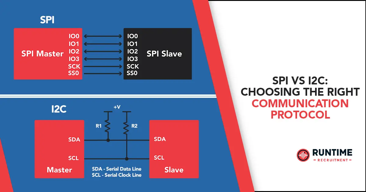
- Signal Lines: SPI employs a four-wire interface:
- MOSI (Master Out, Slave In): Carries data transmitted from the master device.
- MISO (Master In, Slave Out): Carries data received by the master device from slaves.
- SCK (Serial Clock): Provides a dedicated clock signal to synchronize data transfer between the master and slave devices. This dedicated clock simplifies timing control for the master.
- SS (Slave Select): A separate SS line is required for each slave device to enable individual selection for communication. This additional line per slave can become a constraint in designs with limited I/O resources.
- Data Format: SPI data transfer typically occurs in byte (8-bit) chunks. The master initiates a communication sequence by asserting the appropriate SS line for the target slave. Data is then framed with a leading clock pulse (often referred to as a CS, Chip Select, pulse) and a trailing clock pulse. The number of clock cycles per byte transfer is configurable, with some implementations supporting variable-length data frames. Error-checking mechanisms like CRC (Cyclic Redundancy Check) can be implemented in some SPI variations, but are not inherent to the base protocol.
I2C (Inter-Integrated Circuit)
- Architecture: I2C embraces a more flexible approach, supporting multi-master and multi-slave configurations. This allows for complex system designs where multiple devices can initiate communication, acting as either master or slave depending on the situation. However, only one master can actively transmit data at a time due to the half-duplex nature of the protocol.
- Data Transfer Mode: I2C operates in half-duplex mode, meaning data can only flow in one direction at a time – either from the master to the slave or vice versa. The master controls the data direction by initiating and terminating transmissions with Start and Stop bits. This shared communication channel introduces a slight performance bottleneck compared to SPI.
- Signal Lines: I2C utilizes a two-wire interface:
- SCL (Serial Clock): A single clock line shared by all devices on the bus. The master controls the clock signal to synchronize data transfer.
- SDA (Serial Data): A bidirectional data line shared by all devices on the bus for transmitting and receiving data. This shared line necessitates open-drain outputs on all connected devices to avoid bus contention issues. Pull-up resistors are required on the SDA and SCL lines to establish a logic high voltage level.
- Data Format: I2C data transfer typically occurs in byte (8-bit) chunks. The master initiates a communication sequence with a Start bit, followed by a slave address to identify the target device. The addressed slave acknowledges its presence with an ACK (Acknowledge) bit. Data bytes are then transmitted serially, with each byte followed by an ACK bit from the receiving device to confirm successful reception. A Stop bit signifies the end of the transmission. Error checking is implemented through the ACK/NACK (Not Acknowledge) mechanism, allowing devices to signal data reception errors.
In-Depth Analysis
Performance Comparison
- Speed: SPI’s dedicated clock line and full-duplex operation enable significantly faster data transfer rates compared to I2C. SPI benchmarks can exceed 100 Mbps in ideal conditions, while I2C typically operates in the range of 100 kbps to a few Mbps. This speed advantage makes SPI the clear choice for applications demanding high-throughput communication, such as interfacing with high-resolution displays or fast ADCs.
- Latency: Due to the master-slave architecture and additional overhead associated with slave selection in SPI, I2C can offer lower latency for short data transfers. In I2C, once the bus is established and the target slave is addressed, data transfer can occur relatively quickly without the need for individual slave selection.
- Real-Time Performance: For applications requiring deterministic and predictable data transfer timing, SPI’s dedicated clock line offers a slight advantage. The master controls the SCK line, ensuring precise data synchronization between itself and the slave(s). I2C’s shared clock line introduces some dependence on the clock stretching capability of slave devices, which can introduce minor variations in data transfer timing.
Hardware Complexity
- SPI: The simpler master-slave architecture and dedicated data lines of SPI translate to a slightly less complex hardware design compared to I2C. The master device only requires logic for data formatting, transmission, and reception, while slave devices primarily focus on data reception and transmission based on master commands. However, routing the additional wires for SPI on the PCB can introduce layout challenges, especially in space-constrained designs with multiple slave devices requiring individual SS lines.
- I2C: With its shared clock and data lines (SDA and SCL), I2C necessitates a slightly more intricate hardware design due to the open-drain configuration. Open-drain outputs allow multiple devices to drive the bus without contention, but require pull-up resistors to establish a logic high voltage level. This additional circuitry adds some complexity compared to SPI. However, the benefit lies in the reduced number of PCB traces needed, making I2C a more attractive option for designs with limited routing space.
Scalability
- SPI: SPI’s point-to-point nature limits its ability to connect to a large number of devices due to the requirement of a dedicated SS line for each slave. Workarounds like daisy-chaining can be implemented to connect multiple slaves on a single bus, but this introduces additional complexity and potential signal integrity issues as the signal travels through multiple devices.
- I2C: I2C shines in scalability due to its multi-master and multi-slave capability. The use of slave addresses allows for the connection of numerous peripherals on a single bus, making it ideal for complex systems with a multitude of sensors and actuators. However, as the number of devices on the bus increases, potential bus contention issues can arise, requiring careful design considerations to manage data access and avoid collisions.
Power Consumption
- SPI: SPI’s higher data transfer speeds naturally translate to increased power consumption, particularly at high clock frequencies and with large data packets. The continuous operation of the SCK line and data transfers contribute to higher dynamic power consumption. However, optimizations like reducing clock speed and employing data buffering techniques can help mitigate this impact.
- I2C: I2C generally consumes less power than SPI due to its lower operating speeds and simpler hardware design. The shared clock line and half-duplex operation contribute to lower overall power consumption. This makes I2C a compelling choice for low-power applications where extending battery life is crucial.
Application Considerations
| Feature | SPI | I2C |
| Interface | Four-wire (MOSI, MISO, SCK, SS) | Two-wire (SCL, SDA) |
| Mode | Full-duplex | Half-duplex |
| Speed | High (over 100 Mbps) | Lower (100 kbps to a few Mbps) |
| Latency | Higher (slave selection overhead) | Lower (for short data transfers) |
| Real-time Performance | More predictable (dedicated clock) | Less predictable (clock stretching) |
| Hardware Complexity | Lower | Slightly higher (open-drain) |
| Scalability | Limited (point-to-point) | High (multi-master, multi-slave) |
| Power Consumption | Higher (faster speeds) | Lower (slower speeds) |
Real-World Application Scenarios
- High-Speed Data Acquisition: When dealing with high-bandwidth data streams, such as those from high-resolution displays or fast ADCs, SPI’s superior speed and real-time performance make it the preferred choice.
- Low-Power Sensor Communication: For interfacing with multiple low-power sensors or simple peripherals where speed is less critical, I2C’s lower power consumption and efficient pin usage are advantageous.
- Complex System Integration: In systems with a multitude of sensors and actuators requiring communication, I2C’s multi-master and multi-slave capability allows for a more scalable and flexible design. However, careful bus management techniques are crucial to avoid data collisions, especially as the number of devices increases.
Additional Factors to Consider
- Existing Device Support: Some peripheral devices may have built-in support for only one protocol (SPI or I2C). This can influence the choice based on compatibility needs. For example, many memory devices like EEPROMs typically come with a dedicated SPI interface.
- Software Libraries: The availability of mature and well-supported software libraries for a particular protocol on the chosen microcontroller can simplify development and reduce integration time. Established libraries often handle communication details like data formatting, error checking, and slave selection (for SPI), reducing development effort.
Conclusion
Understanding the strengths and weaknesses of both SPI and I2C is essential for embedded systems engineers. SPI reigns supreme in speed, making it ideal for high-throughput applications demanding real-time performance. However, its increased pin count and power consumption can be drawbacks. I2C shines in space-constrained designs and low-power scenarios with its efficient pin usage and multi-device support. By carefully evaluating factors like performance requirements, scalability needs, power constraints, and existing device compatibility, engineers can make informed decisions when selecting the optimal communication protocol for their specific application.
Hire the Best Engineers with RunTime
At RunTime, we are dedicated to helping you find the best Engineering talent for your recruitment needs. Our team consists of engineers-turned-recruiters with an extensive network and a focus on quality. By partnering with us, you will have access to great engineering talent that drives innovation and excellence in your projects.
Discover how RunTime has helped 423+ tech companies find highly qualified and talented engineers to enhance their team’s capabilities and achieve strategic goals.
On the other hand, if you’re a control systems engineer looking for new opportunities, RunTime Recruitment’s job site is the perfect place to find job vacancies.
References
- Microchip Technology, “Serial Peripheral Interface (SPI)”
- NXP Semiconductors, “I2C-bus specification”
- Texas Instruments, “Introduction to Serial Communication Protocols“


