Ever spent weeks, maybe months, meticulously crafting a prototype that works flawlessly on your desk? You’ve debugged every line of code, tuned every peripheral, and the LEDs blink in perfect harmony. You’re ready for the big leagues—production. The design is finalized, the gerbers are sent, and the first batch of production boards arrives. With bated breath, you flash the same firmware you used on the prototype, expecting the same magic. But… it’s not the same. The boot-up sequence is flaky, a sensor is giving wonky readings, or a critical function just doesn’t work. Welcome to the frustrating, all-too-common world of hardware configuration drift.
This isn’t just bad luck; it’s a systemic problem rooted in the complex interplay between design, components, manufacturing, and software. This article delves deep into the “why” behind this phenomenon, offering a comprehensive guide for embedded engineers to anticipate, diagnose, and mitigate these issues.
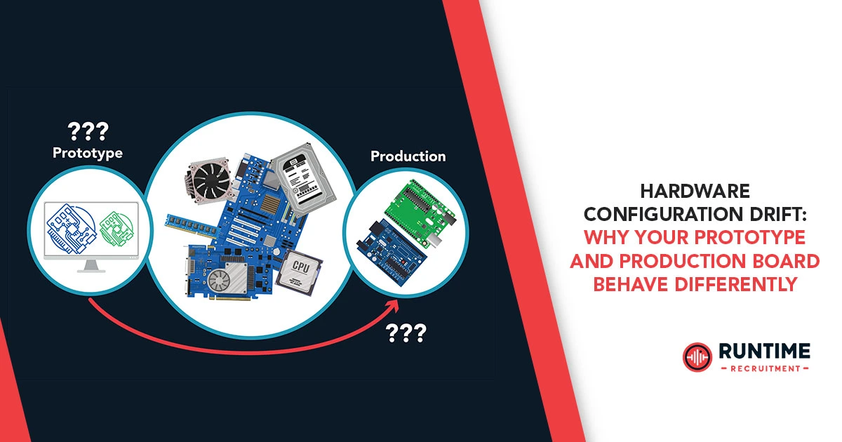
The Myth of the Identical Twin
At the heart of the problem lies a fundamental misconception: that all boards produced from the same design file are identical. While they may share the same schematic and PCB layout, the reality is far more nuanced. Each component, each manufacturing process, and each environmental factor introduces subtle variations. When these variations accumulate, they can push a system out of its functional tolerance window, leading to the bizarre and unpredictable behavior we call configuration drift.
The Culprits: A Deep Dive into the Sources of Drift
Hardware configuration drift can be traced back to several key areas. Understanding these sources is the first step toward building more robust and reliable products.
1. Component Variation: The “Invisible” Tolerance Stack-Up
Every electronic component, from a humble resistor to a complex microcontroller, has manufacturing tolerances. A 10kΩ resistor isn’t exactly 10,000Ω; it’s a value within a specified range, say ±1%. While this variation is insignificant for many applications, in a high-speed or precision circuit, the cumulative effect can be disastrous.
- Passive Components: Resistors, capacitors, and inductors have specified tolerances. A 5% capacitor on your prototype might be 4.5% on one production board and 5.5% on another. In a timing circuit, this seemingly small difference can alter a critical RC time constant, affecting clocking or reset behavior. In a filter, it can shift the cutoff frequency, leading to unexpected signal degradation. The same applies to inductors in power converters, where slight inductance variations can impact switching performance and efficiency.
- Active Components: Microcontrollers (MCUs) and other complex chips are a major source of variation. Parameters like internal oscillator frequency, ADC reference voltage, I/O pin drive strength, and even internal flash memory timing can vary from one chip to the next, even within the same batch.
- Internal RC Oscillators: Many low-cost MCUs use internal RC oscillators for their clock source. The frequency of these oscillators is highly sensitive to process variations, temperature, and supply voltage. A firmware calibrated on a prototype with an oscillator running at 16.1 MHz might fail on a production board with one at 15.9 MHz, especially in time-critical protocols like UART or I2C.
- Analog Peripherals: The performance of ADCs and DACs is not uniform. The effective number of bits (ENOB), linearity, and offset can vary. If your prototype’s ADC has a high ENOB and low offset, your firmware might assume high accuracy. A production board with a “standard” or lower-spec chip might have significant offset, requiring a firmware calibration routine that was never developed.
- Component Sourcing and Supply Chain: The global semiconductor market is complex. The same part number from different manufacturers (e.g., a common MOSFET or op-amp) might have slightly different characteristics, even if they meet the datasheet specifications. Furthermore, even from the same manufacturer, chips produced at different fabrication plants or at different times can exhibit minor process variations. The “same” part you used in your prototype might come from a different batch, or even a different foundry, for your production run. This is a common issue with mass production where supply chains are optimized for cost and availability.
2. PCB Layout and Manufacturing Imperfections: The Physical Reality
The PCB isn’t just a platform; it’s an integral part of the circuit. Imperfections introduced during manufacturing can fundamentally alter the board’s electrical properties.
- Trace Impedance and Length: High-speed signals, like those in USB, Ethernet, or DDR memory, are highly sensitive to trace impedance and length. Minor variations in trace width, copper thickness, or the dielectric constant of the PCB substrate can change the impedance, leading to signal reflections and integrity issues. While a prototype board might be perfectly tuned, a production run might have subtle variations in the etching process, causing your high-speed communication link to fail.
- Differential Pairs: For differential signals, a mismatch in the length of the positive and negative traces can cause skew, degrading the signal quality and introducing EMI. While your design might be perfectly symmetric, the manufacturing process might not be.
- Solder Joint Quality and Paste Mask: The quality of solder joints is critical for reliable electrical and mechanical connections. During mass production, variations in solder paste deposition, reflow oven temperature profiles, and component placement can lead to:
- Cold Solder Joints: Poorly melted solder that forms a brittle, high-resistance connection. This can manifest as intermittent behavior, where a component works one minute and fails the next.
- Bridging: Solder accidentally connecting two adjacent pads. This is a common cause of shorts and can be particularly hard to debug.
- Voids: Pockets of air trapped in the solder joint. These can reduce the thermal and electrical conductivity of the joint.
- Vias and Stack-up: The resistance and inductance of vias (the holes that connect different layers of the PCB) can vary. In sensitive analog or RF designs, this can be a major source of drift. The stack-up itself, the thickness and type of insulating material between layers, can also vary slightly, impacting the overall electrical characteristics of the board.
3. Software Assumptions and Unvalidated Configurations: The Code’s Blind Spots
Your firmware, while technically correct, often makes implicit assumptions about the hardware that are only true for your specific prototype. When those assumptions are challenged by the subtle variations of a production board, the software fails.
- Fixed-Value Calibrations: A common mistake is to hard-code calibration values derived from a single prototype. For example, if you measure the output of a sensor on your prototype and find a specific offset, you might hard-code that value into your firmware. On a production board, the sensor and the ADC might have different offsets, making your hard-coded value incorrect. The solution is always to implement a dynamic calibration routine that measures and adjusts for these variations at run-time or during a factory test.
- Timing Assumptions: Firmware often relies on precise timing. If your code uses a busy-wait loop for a specific duration, it implicitly assumes the MCU’s clock speed is exact. If the production MCU’s internal oscillator is off by even a small percentage, the timing of your software will be incorrect, leading to communication failures, missed events, or incorrect PWM duty cycles. Using hardware timers and interrupts, which are based on the clock, is a much more robust solution than relying on software delays.
- Power-On Reset and Brown-Out Detection: The behavior of power-on reset (POR) and brown-out detection (BOD) can be a source of drift. The exact voltage at which a BOD circuit triggers can vary. If your prototype board has a clean power supply ramp-up, and your production board has a slower, noisier one, the BOD might trigger prematurely or fail to trigger, leading to a hang or an invalid state. Your firmware should be robust enough to handle these power-up variations.
- Non-Uniform Boot-Up States: Different MCUs from the same family might have slight variations in their boot-up sequence or default register values. While the datasheet specifies a set of defaults, minor differences can exist. Your firmware needs to explicitly initialize all necessary peripherals and registers, rather than relying on their default power-up state.
The Mitigation Strategy: From Prototype to Production
Avoiding hardware configuration drift isn’t about luck; it’s about a disciplined engineering approach that starts at the design phase.
1. Design for Manufacturability (DFM) and Testability (DFT)
- Account for Tolerances: When selecting components, consider their tolerances and how they will impact the circuit. Use worst-case analysis to ensure your design functions correctly even with components at the extremes of their specified ranges. Don’t assume a 5% resistor will be exactly 5%; assume it will be anywhere from 4.75% to 5.25%.
- Decoupling and Power Integrity: Use adequate decoupling capacitors and pay careful attention to power and ground planes. A robust power delivery network can absorb a lot of the noise and variation that might otherwise lead to drift.
- Test Points: Add test points to your design for critical signals, power rails, and I/O. This makes it easier to test the board on a production line and diagnose issues. A good design includes a test fixture that can quickly and reliably verify key functionality.
2. Robust Firmware and Software Development
- Dynamic Calibration: Instead of hard-coding values, implement a one-time or run-time calibration routine for sensors, ADCs, and internal oscillators. This allows each board to self-adjust to its unique component variations. For example, you can measure the internal bandgap voltage of the MCU to calibrate the ADC reference.
- Hardware Abstraction Layer (HAL): Use a well-defined HAL to abstract away the low-level hardware specifics. This makes your code more portable and less susceptible to minor hardware changes.
- Defensive Programming: Don’t rely on implicit assumptions. Always initialize registers, check return codes from functions, and use watchdog timers to recover from unexpected hangs.
3. Manufacturing and Quality Control
- Communication with Your CM: Work closely with your contract manufacturer (CM). Provide them with clear documentation, including a comprehensive Bill of Materials (BOM) with approved manufacturers and part numbers. Specify a robust solder reflow profile and inspection criteria.
- Rigorous Testing: Implement a thorough end-of-line (EOL) test for every single board produced. This test should go beyond a simple “power-on” check. It should exercise every peripheral and validate critical performance metrics. This is your last line of defense against drift.
- Traceability: Implement a system to trace each board back to its manufacturing batch, component lot numbers, and test results. If a failure occurs in the field, this traceability is invaluable for diagnosing the root cause.
Conclusion: The Road to Production Nirvana
Hardware configuration drift is a challenging but manageable problem for embedded engineers. It’s a rite of passage, a lesson learned the hard way that a prototype is a proof of concept, not a guarantee of production success. By understanding the sources of variation—from component tolerances to manufacturing imperfections and software assumptions—you can build systems that are not only functional but also robust, reliable, and production-ready.
The path from a single prototype to thousands of identical, working units is paved with careful design, rigorous testing, and an unwavering commitment to quality. The “magic” you created on your desk can be replicated, but only if you respect the reality of the physical world and engineer your way around its inherent imperfections.
Looking for your next engineering challenge? Ready to apply your expertise in building robust, production-ready systems? Connect with us at RunTime Recruitment. We specialize in matching top-tier embedded engineers with companies who value their skills and experience. Your next great role is just a conversation away.


