The world of embedded systems is undergoing a profound transformation. As billions of devices—from tiny IoT sensors to complex automotive ECUs—become interconnected, the need for robust, device-specific security has skyrocketed. The traditional methods of storing cryptographic keys in Non-Volatile Memory (NVM) are proving insufficient against sophisticated invasive and side-channel attacks. For the discerning embedded engineer, the solution lies in a concept that’s as fundamental as the silicon itself: Hardware-Backed Identity anchored by Physically Unclonable Functions (PUFs).
PUFs are the silicon equivalent of a biometric fingerprint. They leverage the uncontrollable, random manufacturing variations inherent in every chip to generate a unique, non-clonable digital signature. This blog article dives deep into the architecture and, crucially, the software-centric implementation of PUFs, transforming them from a hardware curiosity into the keystone of a secure embedded design.
The Inviolable Fingerprint: Understanding the PUF Core
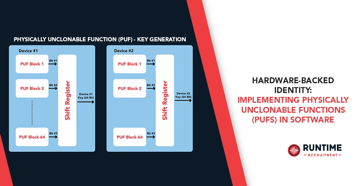
At its heart, a Physically Unclonable Function is a circuit that, for a given input (a Challenge), produces a unique, device-specific output (a Response). This challenge-response pair (CRP) is a function of the micro-scale physical and electrical characteristics of the integrated circuit—variations so minute they are impossible to reproduce even with the most advanced manufacturing processes.
Key PUF Characteristics:
| Characteristic | Description | Significance for Security |
| Uniqueness (Inter-Chip Variation) | The responses from different PUF instances, even those from the same batch, are statistically uncorrelated. | Ensures that no two devices share the same root key or identity. |
| Randomness (Intra-Chip Entropy) | The response bits are random, exhibiting a near 50/50 balance of 0s and 1s. | Provides a high-entropy source suitable for cryptographic key generation. |
| Reliability (Intra-Chip Stability) | The same PUF instance generates the same response for a given challenge under varying operational conditions (temperature, voltage, aging). | Essential for repeatable, functional key generation; this is the biggest engineering challenge. |
| Unclonability | The physical process variations are practically impossible to measure and replicate, preventing an adversary from building an identical PUF. | Protects against physical attacks, as the secret is in the physics, not in stored data. |
The Dominant Architecture: The SRAM PUF
While there are many PUF types (Arbiter PUF, Ring Oscillator PUF, etc.), the Static Random-Access Memory (SRAM) PUF has emerged as a powerhouse, particularly for embedded systems. This is primarily because most embedded microcontrollers already contain SRAM, negating the need for custom hardware IP.
SRAM PUF Mechanism: A standard SRAM cell is a cross-coupled latch that, upon power-up, resolves to one of two stable states, ‘0’ or ‘1’. This initial state is dictated by minute, random differences in the threshold voltages (Vth) and gain factors (β) of the cell’s six transistors. Due to these manufacturing variations, one side of the latch will always be slightly stronger, causing the cell to preferentially power up to a specific state. Reading the initial power-up state of a block of uninitialized SRAM thus yields a unique, high-entropy bit string—the PUF response.
The simplicity and ubiquity of the SRAM PUF make it the prime candidate for software implementation, which is where the embedded engineer steps in.
The Software Layer: Bridging the Hardware Gap
The core PUF function is hardware-based, but its transformation into a reliable, functional cryptographic key or device identity is a purely software-driven process. The software must execute three critical functions: measurement, enrollment, and reconstruction. This process is often collectively managed by a PUF Security IP block or, in the case of simple SRAM PUFs, entirely by firmware running in a Trusted Execution Environment (TEE) or Secure Element.
Step 1: Measurement and Enrollment
The enrollment phase is where the device’s unique fingerprint is first captured and characterized. This typically happens once, either in a secure factory environment or during the first boot-up.
- Raw PUF Response Acquisition: The software issues a power-cycle or a reset to the designated SRAM block. A quick read operation captures the raw, uninitialized power-up state. This raw response, Rraw, is the device’s unique fingerprint.
- Characterization and Helper Data Generation: The raw response is highly unique but suffers from instability. Environmental factors (temperature, voltage) and aging can cause a small percentage of bits—known as flaky bits—to flip inconsistently.
- Bit Selection: The software measures the raw response multiple times under various worst-case environmental conditions (or simulated conditions like varying power-down/power-up timings, a technique called Data Remanence). Bits that flip are marked as unreliable. A sophisticated algorithm then selects only the stable bits to form the final, high-quality key.
- Fuzzy Extractor: To correct the remaining few unstable bits and protect the key, a Fuzzy Extractor algorithm is employed. The Fuzzy Extractor is a crucial software primitive, typically built on an Error Correction Code (ECC) like Bose-Chaudhuri-Hocquenghem (BCH) or Reed-Muller codes.
- It takes the noisy raw response (Rraw) and generates two outputs: the stable, secret cryptographic key (K) and a piece of public, non-secret data called the Helper Data (W).
- The mathematical relationship is: W=Rraw⊕ECC_syndrome(Rraw).
- The Helper Data W is derived from the Rraw but reveals nothing about the secret key K. It is typically stored in standard NVM (like eFuse or Flash), as it is not secret. The security relies on the fact that an attacker cannot recover Rraw or K from W.
The software’s role in this phase is the precise control of power and timing, the statistical analysis of bit stability, and the execution of the computationally intensive Fuzzy Extractor to distill a perfect key K and its public Helper Data W.
Step 2: Key Reconstruction and Real-Time Operation
The true utility of a PUF lies in its ability to regenerate the identical secret key K on demand, at run-time, without ever storing it in NVM. This is the reconstruction phase.
- New Raw Response: When the system requires the key (e.g., for secure boot, firmware decryption, or TLS session establishment), the software triggers a new power-up of the SRAM block to generate a new raw response, Rraw′. Due to noise and environmental drift, this Rraw′ will be slightly different from the original Rraw used during enrollment.
- Error Correction: The software retrieves the public Helper Data (W) from NVM and feeds both Rraw′ and W into the Fuzzy Extractor’s decoder (the Reproduce function).
- The decoder uses the Helper Data W to correct the few bit errors in Rraw′.
- The logic is: Reconstructed Key K′=Decode(Rraw′,W).
- Perfect Key Regeneration: If the number of bit errors is within the ECC’s correction capability (e.g., typically less than 1-2%), the decoder reconstructs a perfectly identical copy of the original secret key, K′=K.
The key is generated dynamically, used for the cryptographic operation, and then immediately erased from the volatile SRAM/register memory. This concept of zero-storage key management is the foundation of PUF-backed security.
Software Challenges for the Embedded Engineer
Implementing a PUF, even one as accessible as the SRAM PUF, presents several software-centric challenges that must be meticulously engineered.
A. Reliability and Environmental Compensation
The sensitivity of the raw PUF response to temperature (ΔT), voltage (ΔV), and aging is the single greatest hurdle. A key flip means an authentication failure or a corrupt cryptographic key.
- Software Mitigation: Dynamic Measurement Control
- Temperature Compensation: Implement software to read the current die temperature (via an on-chip sensor) and apply a pre-characterized Challenge Tuning or Compensation Table. For example, at higher temperatures, the software might dynamically adjust the SRAM power-up time or voltage reference to ensure maximum stability.
- Age-Related Flakiness: Ageing (e.g., Bias Temperature Instability, BTI) can cause bit flips over the device’s lifetime. Advanced software can incorporate a Health Monitor to periodically re-verify PUF stability and, if necessary, update the Helper Data in the field via a secure update protocol (though this is complex).
B. Security Against Side-Channel Attacks (SCAs)
While the PUF response is not stored, the act of key reconstruction can expose the process to SCAs, such as Differential Power Analysis (DPA). An attacker measures the tiny power consumption differences during the ECC processing of Rraw′ and W to guess the secret key.
- Software Mitigation: Masking and Randomization
- Randomization of Measurement: Introduce a random element to the timing or location of the PUF measurement. For instance, the software could randomly shift the physical SRAM block used as the PUF source.
- Masking in ECC: The ECC operation itself must be protected. Standard practice involves masking the intermediate data: K is never processed directly, but as K⊕M, where M is a cryptographically secure random mask. The final result is de-masked only at the last step. Implementing these high-assurance cryptographic primitives correctly in C/C++ requires a deep understanding of low-level CPU operations and compiler-specific optimizations to avoid inadvertent side-channel leaks.
C. Resource Constraints and Performance Overhead
Embedded engineers in the IoT space often deal with microcontrollers that are severely constrained in memory and processing power. ECC algorithms and the Fuzzy Extractor’s Decode function are computationally expensive, adding latency to the secure boot process—a critical metric for user experience.
- Software Mitigation: Hardware Acceleration and Optimized Code
- Leveraging Hardware Accelerators: Where available, the software should offload the ECC and other cryptographic hash operations (e.g., SHA-256 for key derivation) to on-chip hardware accelerators to minimize execution time and power consumption.
- Optimized Assembly: For the most time-critical sections of the Fuzzy Extractor, hand-optimized assembly language can provide significant speedups over compiler-generated C code, directly impacting the overall boot time. The engineer must strike a balance between performance, code complexity, and maintainability.
Practical Application: The Hardware-Backed Root of Trust (HRoT)
The successful software implementation of a PUF provides the single most critical component for a modern security architecture: the Hardware Unique Key (HUK). This HUK, derived only from the PUF, is the anchor for the entire Hardware Root of Trust (HRoT).
- Unique Device Identification (UID): The HUK can be used as the device’s unforgeable, globally unique identifier for asset tracking, inventory management, and cloud provisioning.
- Secure Key Provisioning and Storage: The HUK is the root key. All other keys—device encryption keys, firmware decryption keys, and session keys—are generated by feeding the HUK into a Key Derivation Function (KDF), often combined with other non-secret parameters. This means no secret key is ever stored in persistent memory; they are all derived dynamically from the HUK.
- Secure Boot: The first stage bootloader is authenticated by a signature that is verified using a public key whose private counterpart is secured by the PUF-derived HUK. This establishes an unbroken Chain of Trust from the silicon up to the application layer.
- IP Protection and Software Binding: By encrypting proprietary firmware with the device’s HUK, the software is cryptographically bound to a specific, unique chip. Cloning the firmware and flashing it onto another device fails because the second device’s PUF will produce a different HUK, leading to a decryption failure. This is an essential defense against Intellectual Property (IP) theft and overproduction.
For the embedded engineer, the implementation of PUF-based security is a shift from merely storing secrets to generating and deriving secrets on demand. It requires a comprehensive approach, where low-level software has total control over the physical and electrical parameters of the silicon to ensure reliability and attack resistance.
Conclusion: Securing the Next Generation of Embedded Devices
The era of simple NVM key storage is over. As threats become more sophisticated and physical access to devices becomes commonplace, Hardware-Backed Identity via PUFs is becoming a mandatory design principle.
Implementing a PUF in software is a complex but immensely rewarding engineering task. It demands expertise in low-level driver development, advanced error correction codes, and a deep understanding of cryptographic security vulnerabilities like side-channel attacks. The ability to successfully manage the lifecycle of the PUF—from initial enrollment to robust, reliable key reconstruction in the field—separates competent embedded development from world-class security engineering.
This is where the future of embedded security is being built: not just in the custom hardware, but in the sophisticated software that harnesses the immutable laws of silicon physics. By mastering the concepts of the Fuzzy Extractor, Challenge Tuning, and side-channel countermeasures, you are creating systems that are secure by design, not just by policy.
Ready to tackle the next generation of embedded security challenges, including the complex world of PUF integration?
Connect with RunTime Recruitment today to find opportunities that push the boundaries of hardware-backed security and cryptographic engineering.


