In embedded systems, automation reigns supreme. But behind every smoothly running machine lies a control system, its intricate dance of inputs, outputs, and processing elements meticulously documented in schematics. For embedded systems engineers, understanding these schematics is not a luxury, it’s a necessity.
Why Schematics Matter
Control system schematics are the blueprints of automation. They provide a clear visual representation of how various components interact to achieve a desired control function. This knowledge empowers engineers in several ways:
- Efficient Troubleshooting: When a system malfunctions, schematics become the roadmap to pinpoint the culprit. By tracing signal flow and analyzing component interactions, engineers can diagnose problems swiftly, minimizing downtime.
- Informed Design Decisions: Integrating new components or modifying existing systems requires a grasp of the overall control scheme. Schematics provide the context needed to make informed decisions about compatibility and functionality.
- Enhanced System Maintenance: Effective preventive maintenance plans rely on a thorough understanding of the system’s intricacies. Schematics guide engineers in identifying critical components and scheduling maintenance tasks accordingly.
Demystifying the Symbols
The language of control system schematics revolves around symbols. Familiarity with these symbols is paramount.
- Standard Symbol Libraries: Industry standard libraries, such as IEEE or IEC, define symbols for common components like resistors, capacitors, transistors, and integrated circuits. Understanding these basic building blocks is essential.
- Manufacturer Datasheets: For specific components, manufacturer datasheets provide detailed pinouts and functional descriptions. Referencing these datasheets alongside the schematic symbol unlocks a deeper understanding of the component’s role.
- Ladder Logic Symbols: A crucial subset of symbols resides in the realm of ladder diagrams, a popular format for representing control logic. Recognizing symbols for relays, contacts, and coils becomes critical for deciphering the program flow within the control system.
Navigating the Schematic Landscape
Once the symbolic language is grasped, it’s time to conquer the schematic itself. Here’s how to approach this visual representation:
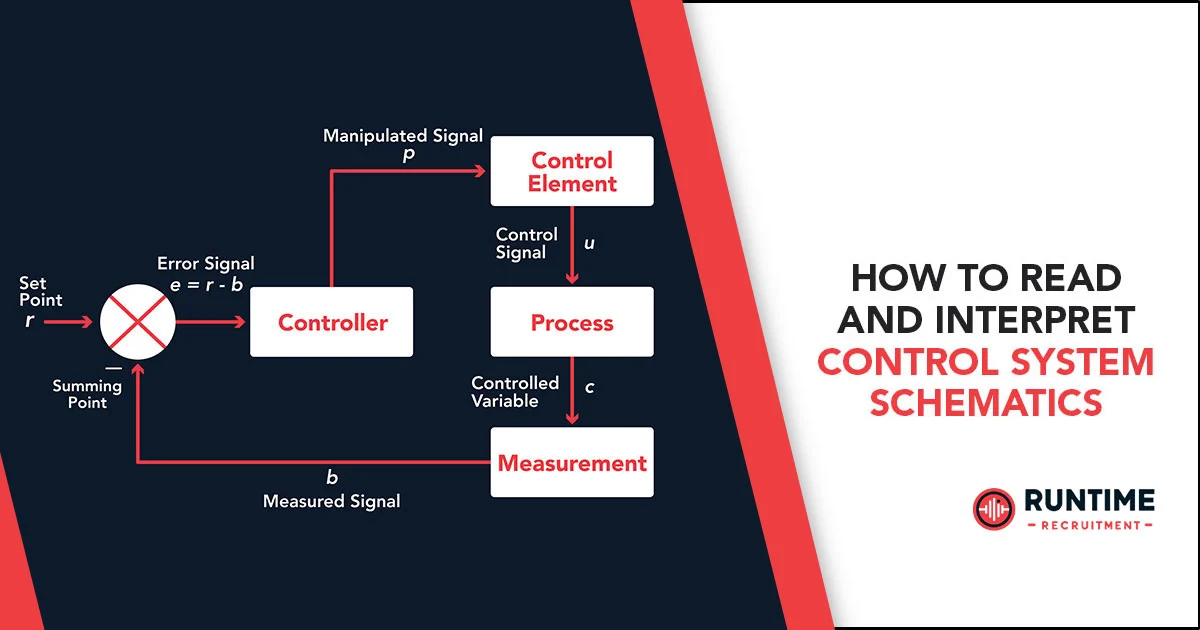
- Signal Flow Analysis: Trace the flow of signals through the schematic. Identify input points (sensors, switches), processing elements (controllers, PLCs), and output elements (motors, actuators).
- Connective Tissue: Wires, buses, and power supplies form the connective tissue of the schematic. Understand how these elements establish communication paths between components.
- Notational Nuances: Schematics are peppered with notations that provide vital context. Reference designators (e.g., R1, C2) uniquely identify components, while wire labels track signal names. Voltage levels are often indicated to ensure proper component selection and operation.
Advanced Concepts
For those seeking to truly master control system schematics, venturing into advanced concepts is key:
- Ladder Diagram Logic: Ladder diagrams depict control logic using rungs (horizontal bars) that represent control sequences. Analyze series and parallel connections within rungs to grasp the overall program flow. Familiarize yourself with common control functions like timers and counters, represented by specific symbols within the ladder logic.
- Function Block Diagrams: Function block diagrams offer a higher-level view of the system, focusing on information flow and system functionality rather than individual component connections. Understanding these diagrams allows engineers to grasp the broader system purpose and how individual control loops contribute to the overall objective.
Putting Theory into Practice
So, you’ve familiarized yourself with the symbols, notations, and advanced concepts – now what? Here’s how to leverage this knowledge:
- Analyzing Existing Systems: The next time you encounter an unfamiliar control system, grab the schematic. Use your newfound skills to trace signal flow, identify control logic, and understand the overall system operation.
- Troubleshooting Techniques: Schematics become powerful troubleshooting tools. By analyzing component interactions and signal flow, engineers can identify potential bottlenecks or component failures based on the schematic itself.
Wrapping Up
The ability to read and interpret control system schematics is an invaluable asset for any embedded systems engineer. By mastering this skill, you gain a deeper understanding of automated systems, streamline troubleshooting efforts, and make informed decisions when designing, maintaining, or modifying control systems.
For those eager to learn further, a wealth of resources awaits you. Online tutorials and textbooks offer comprehensive training, further solidifying your grasp of this essential skill. So, the next time you encounter a control system schematic, don’t be intimidated – approach it with confidence, knowing you possess the tools to unlock its secrets.
Hire the Best Engineers with RunTime
At RunTime, we are dedicated to helping you find the best Engineering talent for your recruitment needs. Our team consists of engineers-turned-recruiters with an extensive network and a focus on quality. By partnering with us, you will have access to great engineering talent that drives innovation and excellence in your projects.
Discover how RunTime has helped 423+ tech companies find highly qualified and talented engineers to enhance their team’s capabilities and achieve strategic goals.
On the other hand, if you’re a control systems engineer looking for new opportunities, RunTime Recruitment’s job site is the perfect place to find job vacancies.


