In the intricate world of embedded systems, where real-time performance and efficient resource utilization reign supreme, the microcontroller’s Central Processing Unit (CPU) often bears the brunt of complex operations. However, for automated measurement systems – critical applications demanding precise timing, synchronous data acquisition, and minimal latency – relying solely on CPU intervention can quickly become a bottleneck. This is where the often-underutilized power of Peripheral Trigger Chaining steps in, offering a paradigm shift in how we design and optimize these systems.
Imagine a symphony orchestra, where each instrument (peripheral) needs to play its part at the precise moment, triggered not by a conductor (CPU) constantly instructing each musician, but by a cascading series of cues, one instrument’s action directly initiating the next. This, in essence, is the beauty of peripheral trigger chaining. It’s a hardware-centric approach that allows various on-chip peripherals to directly interact and control each other, independent of CPU intervention, leading to faster, more deterministic, and power-efficient automated measurement workflows.
The Achilles’ Heel of CPU-Centric Measurement Systems
Before diving into the mechanics and marvels of trigger chaining, let’s first understand the limitations of traditional CPU-driven measurement systems:
- Latency and Jitter: Every time the CPU needs to initiate a peripheral action (e.g., start an ADC conversion, toggle a GPIO, begin a DMA transfer), it involves context switching, interrupt handling, and executing instruction cycles. This introduces inherent latency and, more critically, jitter – variations in timing that can severely impact the accuracy and repeatability of high-speed or precision measurements.
- CPU Overhead and Resource Contention: Constant CPU involvement in routine peripheral control consumes valuable processing cycles that could otherwise be dedicated to data processing, algorithm execution, or higher-level system tasks. In complex systems, this can lead to CPU saturation and a degradation of overall system performance.
- Power Consumption: Keeping the CPU active for trivial peripheral control burns more power than necessary. In battery-powered or energy-constrained applications, this can significantly shorten operational life.
- Complexity of Software Development: Synchronizing multiple peripherals through software interrupts and flags can lead to convoluted and difficult-to-debug code, increasing development time and the likelihood of timing-related bugs.
The Core Concept: Decentralized Control and Event Propagation
Peripheral trigger chaining, also known by various vendor-specific names like Event System, Programmable Logic Unit (PLU), or Digital Interconnect Matrix (DIM), fundamentally shifts control away from the CPU for specific sequences. At its heart, it leverages dedicated hardware logic to propagate “trigger” or “event” signals between peripherals.
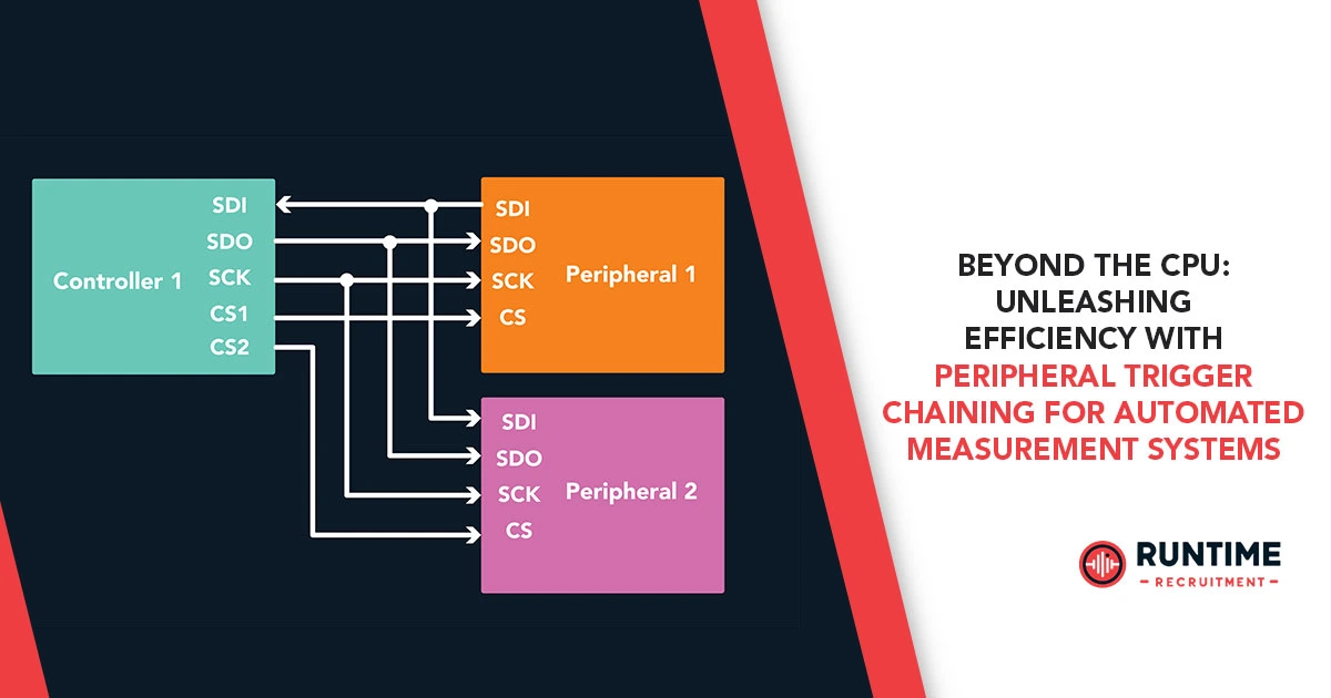
Think of it as a sophisticated, configurable wiring harness within the microcontroller. A trigger source (e.g., a timer overflow, an ADC conversion complete signal, a comparator output, an external GPIO edge) can directly activate a trigger destination (e.g., initiate a DMA transfer, start another timer, capture an input, trigger a PWM update). This direct hardware connection bypasses the CPU entirely for the chained operations.
Anatomy of a Trigger Chain
While implementations vary across microcontroller architectures (e.g., ARM Cortex-M, PIC, AVR, Renesas RX), the fundamental components of a trigger chaining mechanism typically include:
- Event Generators/Trigger Sources: These are peripherals capable of producing a digital pulse or event signal upon the occurrence of a specific condition. Common examples include:
- Timers/Counters: Overflow, underflow, compare match.
- Analog-to-Digital Converters (ADCs): Conversion complete, window comparison.
- Comparators: Output state change (e.g., voltage crossing a threshold).
- Digital-to-Analog Converters (DACs): Buffer empty/full.
- GPIOs: Rising/falling edge detection.
- Communication Peripherals (UART, SPI, I2C): Receive complete, transmit empty.
- Direct Memory Access (DMA) Controllers: Transfer complete, half-transfer complete.
- Quadrature Encoders: Index pulse, phase change.
- Event Consumers/Trigger Destinations: These are peripherals that can be directly controlled or initiated by an incoming event signal. Examples often mirror the trigger sources:
- ADCs: Start conversion.
- Timers/Counters: Start, stop, reset, gate.
- PWM Generators: Update duty cycle, restart period.
- DMA Controllers: Initiate transfer.
- GPIOs: Toggle, set, clear.
- Comparators: Enable/disable.
- Event Routing/Interconnect Matrix: This is the configurable hardware logic that defines which trigger source can activate which trigger destination. It’s often represented as a matrix or a series of multiplexers within the microcontroller’s datasheet. Engineers configure this matrix through special registers during initialization. Some advanced microcontrollers offer more sophisticated routing capabilities, including logic gates (AND, OR, NOT) within the event system to combine multiple trigger conditions.
The Power of Chaining: Real-World Applications in Measurement Systems
The true potential of peripheral trigger chaining shines in automated measurement systems where precise, high-speed, and low-latency operations are paramount. Here are several compelling application examples:
- High-Speed Data Acquisition:
- Scenario: Continuously sample an analog signal at a high rate and transfer the data to memory without CPU intervention.
- Trigger Chain: A timer is configured to generate periodic overflow events. Each timer overflow directly triggers an ADC conversion. Upon completion, the ADC’s “conversion complete” event directly triggers a DMA transfer of the sampled data from the ADC result register to a designated memory buffer. Once the DMA transfer is complete (e.g., a buffer full condition), it can optionally generate an interrupt to the CPU, signaling that a block of data is ready for processing.
- Benefit: Achieves deterministic sampling rates and minimizes latency by eliminating software overhead for each sample. The CPU is only interrupted when a significant block of data is ready, maximizing its availability for signal processing or analysis.
- Synchronized Multi-Channel Measurements:
- Scenario: Simultaneously sample multiple analog channels at a precise moment, perhaps triggered by an external event.
- Trigger Chain: An external trigger signal (e.g., from a sensor, a test fixture) on a GPIO pin directly triggers the simultaneous start of multiple ADCs in a synchronized mode. The “conversion complete” events from all ADCs then trigger a multi-channel DMA transfer into a structured data array.
- Benefit: Ensures true simultaneous sampling across channels, crucial for phase-sensitive measurements or when analyzing correlated signals. Eliminates the timing skew that would inevitably arise from sequential CPU-driven starts.
- Automated Pulse Generation and Measurement:
- Scenario: Generate a precise pulse, then immediately measure a response after a specific delay.
- Trigger Chain: A timer generates a pulse via a PWM output. The “PWM period end” event directly triggers another timer to start counting. When this second timer reaches a specific compare value (representing the desired delay), it triggers an ADC conversion or enables a comparator to capture a signal.
- Benefit: Creates highly accurate and repeatable stimulus-response sequences without CPU overhead, ideal for characterizing transducers, optical sensors, or power electronics.
- Closed-Loop Control with Hardware Determinism:
- Scenario: Implement a fast feedback loop where an ADC measurement directly updates a PWM duty cycle based on a simple comparison, bypassing the CPU for the primary control path.
- Trigger Chain: An ADC conversion complete event directly triggers a comparator. The comparator’s output (e.g., “ADC value above threshold”) directly triggers a PWM module to adjust its duty cycle or disable/enable an output. The CPU can monitor the system at a lower rate or handle higher-level control logic.
- Benefit: Achieves ultra-low latency control loops, crucial for motor control, power supply regulation, or precision actuation, where microsecond-level determinism is required.
- Event-Driven Logging and Diagnostics:
- Scenario: Log critical system parameters or states only when an anomaly occurs, minimizing data storage and processing requirements.
- Trigger Chain: A comparator detects an out-of-range voltage. Its output directly triggers a DMA transfer to capture the ADC readings, timer values, and specific GPIO states into a circular buffer. This can also concurrently trigger another peripheral to set a flag or increment a counter for event tracking.
- Benefit: Reduces the data volume that needs to be continuously processed or stored, making system diagnostics more efficient and timely.
Design Considerations and Best Practices
While highly advantageous, implementing peripheral trigger chaining requires careful planning and understanding of your microcontroller’s capabilities:
- Deep Dive into Datasheets and Reference Manuals: This is non-negotiable. Every microcontroller has a unique event system implementation. Understand the specific trigger sources, trigger destinations, and routing options available. Pay close attention to block diagrams illustrating peripheral interconnections.
- Mapping Your Measurement Workflow: Before writing a single line of code, meticulously map out the sequence of operations in your automated measurement system. Identify which peripheral actions naturally follow others and can benefit from hardware triggering.
- Leverage Hardware Tools (if available): Some IDEs and microcontroller development suites offer graphical tools or configuration wizards to visualize and configure trigger chains, simplifying the process and reducing errors.
- Test Incrementally: Start with simple trigger chains and verify their functionality before building more complex sequences. Use logic analyzers or oscilloscopes to observe the timing of trigger signals and peripheral responses.
- Understand Limitations: Be aware of any limitations on the number of concurrent trigger chains, the types of peripherals that can be interconnected, and the complexity of logic that can be implemented within the event system.
- Hybrid Approaches: Peripheral trigger chaining doesn’t replace the CPU entirely. It offloads repetitive, time-critical tasks, allowing the CPU to focus on complex algorithms, higher-level control, communication protocols, and error handling. A well-designed system often employs a hybrid approach, using trigger chains for core measurement sequences and the CPU for oversight and data processing.
- Error Handling and Safeguards: Consider how the system will react to unexpected events or errors within a trigger chain. While the hardware handles the sequencing, the CPU may still need to be notified for critical failures or out-of-bounds conditions.
- Power Management Integration: Design trigger chains with power efficiency in mind. In some cases, parts of the microcontroller can remain in low-power modes until an event within the chain wakes up the necessary peripherals or the CPU.
The Future is Automated and Autonomous
As automated measurement systems become more sophisticated, integrating more sensors, operating at higher speeds, and demanding greater accuracy, peripheral trigger chaining will transition from a niche optimization technique to a fundamental design principle. It empowers embedded engineers to push the boundaries of real-time performance, reduce system costs, enhance reliability, and drastically improve power efficiency in their designs.
By embracing this hardware-centric approach, we move beyond the traditional CPU-as-commander model, allowing peripherals to autonomously cooperate in a tightly synchronized dance, culminating in measurement systems that are not just automated, but truly intelligent and efficient.
Further Reading:
- “Mastering Embedded Systems Peripherals” by Number Analytics
- Microchip MPLAB Harmony Documentation on “SPI ping pong with DMA Chaining”
- “Automation of the supply chain performance measurement based on multi-agent system” by E. Teimoury and M. Fathian (ResearchGate)
- “Event-triggered tracking control for a class of nonholonomic systems in chained form” (ResearchGate)
Ready to elevate your embedded engineering team?
At RunTime Recruitment, we don’t just fill positions; we build the future of your engineering teams. We specialize exclusively in the embedded engineering space, which means we bring unparalleled depth of knowledge and a vast network of top-tier professionals directly to you.
Connect with us today and let us help you find the right fit for you!


