
High-Fidelity Haptics: Taming Actuator Ringing and Jitter in Next-Gen Wearables
16 July 2026 · Lance Harvie
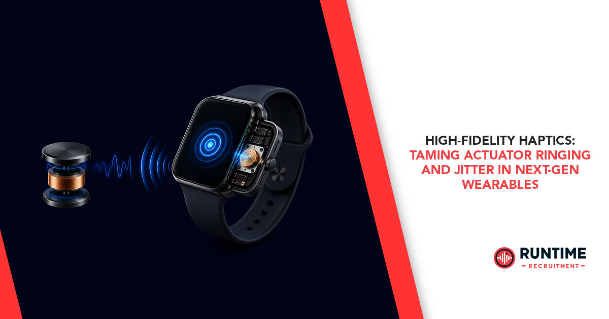
The expectations for wearable device haptics have fundamentally changed. We have moved far beyond the era of crude, monotonous buzzes used purely for basic notifications. Today’s next-generation wearables—ranging from advanced medical monitors and immersive AR/VR controllers to sophisticated smartwatches, demand high-fidelity tactile feedback. Modern user interfaces require haptic subsystems to simulate complex textures, render crisp button clicks, track real-time biometrics, and provide nuanced spatial awareness.
For the embedded systems engineer, delivering this level of fidelity presents a steep physical and algorithmic challenge. At the heart of high-fidelity haptics lies a difficult engineering paradox: how do you achieve rapid, high-acceleration tactile transitions using mechanical components that are inherently prone to resonance, inertia, and latency?
Two primary parasitic phenomena consistently degrade tactile crispness: actuator ringing and temporal jitter. Left unchecked, these issues transform a precise mechanical cue into a muddy, sluggish, or inconsistent user experience.
This deep dive examines the engineering principles, control theory, firmware strategies, and hardware topologies required to tame actuator ringing and jitter, ensuring crisp tactile responses in resource-constrained wearable designs.
The Physics of Tactile Mud: Why Actuators Misbehave
To eliminate unwanted tactile artifacts, we must first understand the electro-mechanical characteristics of modern haptic actuators. While Eccentric Rotating Mass (ERM) motors are still found in low-cost consumer goods, high-fidelity designs rely almost exclusively on Linear Resonant Actuators (LRAs) and Piezoelectric Actuators.
Linear Resonant Actuator (LRA) Structure:
[ Spring ] <---> [ Moving Mass / Magnet ] <---> [ Internal Coil ]
|---> Driven at Resonance Frequency (f_0)
Linear Resonant Actuators (LRAs) and the Resonant Trap
An LRA operates similarly to a loudspeaker. It features a moving mass suspended by internal springs, driven by the magnetic field of a voice coil. LRAs are highly efficient, but this efficiency is entirely dependent on operating at a specific narrow resonant frequency (f0), typically ranging from 150 Hz to 235 Hz.
Because an LRA is a high-Q mass-spring system, it possesses significant mechanical inertia. When an electrical drive signal stops, the suspended mass does not come to an immediate halt. Instead, it continues to oscillate as the stored mechanical energy dissipates through the internal springs. This post-signal oscillation is known as actuator ringing.
In practice, ringing blurs the boundary of a haptic effect. If an engineer programs a sharp 20 ms "click," an uncompensated LRA may continue to ring for an additional 40 ms to 80 ms. To the user, this transforms a crisp, metallic click into a soft, mushy sensation.
Piezoelectric Actuators and High-Capacitance Drive Challenges
Piezoelectric actuators offer a much broader frequency response, faster turn-on times, and higher peak accelerations than LRAs. They operate by deforming a ceramic substrate when an electrical voltage is applied. However, they present a highly capacitive electrical load (often ranging from several hundred nanofarads to microfarads).
While piezos do not suffer from the same spring-mass mechanical resonance limitations as LRAs, they are highly sensitive to electrical drive characteristics. Rapid voltage transitions can trigger high-frequency structural resonances within the piezo element or the device enclosure itself. This results in acoustic noise (audible high-pitched whining or buzzing) and high-frequency structural ringing that degrades the perceived quality of the tactile sensation.
Taming Actuator Ringing: Advanced Drive Mechanics
Defeating mechanical ringing requires active intervention. Relying solely on passive damping is ineffective because it reduces the actuator's peak acceleration, directly undermining its efficiency and tactile impact. Instead, embedded firmware must actively manage the energy within the mechanical system.
Active Braking (Overdrive and Reverse Drive)
The most direct method to eliminate LRA ringing is the application of an explicit braking phase immediately following the active haptic waveform.
When driving an LRA with a standard H-bridge configuration using Pulse-Width Modulation (PWM), accelerating the mass requires a signal driven precisely at f0. To stop the mass instantly, the drive topology must apply an inverted signal (180∘ out of phase) for a calculated duration. This phase-inverted signal acts as an electromagnetic brake, actively counteracting the forward momentum of the internal mass.
LRA Drive Phase Sequence:
[ Overdrive Phase (V_max) ] -> [ Sustain Phase (V_nom) ] -> [ Active Braking Phase (-V_max) ] -> [ Zero Drive ]
Implementing an optimal braking sequence involves three distinct phases:
Overdrive Phase: A high-voltage start-up pulse designed to overcome static friction and mass inertia quickly, bringing the actuator up to target acceleration in minimal time.
Sustain Phase: The nominal drive voltage at f0 that maintains the desired haptic acceleration amplitude.
Active Braking Phase: The phase-inverted pulse applied at maximum amplitude to halt the mass.
The duration of the braking phase must be calibrated precisely. If the braking pulse is too short, the mass continues to ring. If it is too long, the braking pulse re-energizes the mass in the opposite direction, creating a secondary tactile artifact.
Smart Drivers and Real-Time Back-EMF Tracking
Because the resonant frequency (f0) of an LRA shifts dynamically based on temperature, mounting stress, aging, and device orientation, static braking profiles often drift out of calibration. Advanced wearable architectures overcome this by using real-time Back-Electromotive Force (Back-EMF) sensing.
When an LRA mass moves through the voice coil's magnetic field without an active drive current, it functions as a generator, inducing a voltage back across the coil terminals. This Back-EMF voltage is directly proportional to the velocity of the moving mass.
By utilizing a dedicated haptic driver IC or implementing an interleaved sensing routine within the microcontroller's ADC, firmware can sample the Back-EMF during the zero-crossing periods of the PWM drive signal.

Where:
B is the magnetic flux density,
l is the length of the wire coil,
v(t) is the instantaneous velocity of the moving mass.
By tracking the phase and amplitude of the Back-EMF, a closed-loop control loop can dynamically adjust both the driving frequency and the exact duration of the active braking phase. If the Back-EMF signal indicates that the mass is still oscillating after a drive cycle, the controller extends the braking window until the residual velocity reaches zero.
Eliminating Jitter: Synchronizing the Firmware Pipe
While ringing is fundamentally a mechanical and analog control problem, haptic jitter is a digital timing issue. Jitter occurs when the temporal spacing between consecutive haptic updates or wave steps varies unpredictably.
In high-fidelity applications—such as rendering a scrolling wheel texture where tactile pulses must correlate with physical finger movement—even sub-millisecond variations in timing break the user's illusion of reality. If a pulse arrives 2 ms too early or too late, the human mechanoreceptors (specifically Meissner's corpuscles) perceive the anomaly as an uneven, unstable, or low-quality texture.
Sources of Jitter in Modern MCU Architectures
In a typical wearable firmware stack, haptic execution pipelines often conflict with other system tasks. Common sources of latency and jitter include:
Interrupt Latency: High-priority BLE or Wi-Fi network stacks preempting lower-priority haptic timer interrupts.
RTOS Context Switching Overhead: Delays introduced when an RTOS thread wakes up to push a new frame buffer to a haptic driver over an SPI or I2C bus.
Shared Bus Contention: The I2C/SPI bus being blocked by sensor polling tasks (e.g., IMU or heart-rate monitor) when the haptic driver requires immediate data.
Implementing Hard Real-Time Haptic Scheduling
To minimize latency and achieve deterministic haptic timing, the haptic subsystem must be decoupled from non-deterministic application threads.
Firmware Architecture for Jitter Elimination:
[ High-Priority Hardware Timer Interrupt ]
|
v (Direct Register Write or DMA Trigger)
[ Peripherial Bus: SPI / PWM Generation ] ---> [ Dedicated Haptic Driver ]
Hardware-Level Timer Interrupts: Avoid relying on standard RTOS task delays (vTaskDelay). Instead, drive haptic waveform steps using a dedicated hardware timer interrupt configured to the highest allowable priority below critical kernel operations.
DMA-Backed Communications: When streaming complex waveform profiles to external drivers via SPI or I2C, utilize Direct Memory Access (DMA). The timer interrupt should trigger a DMA transfer directly from a pre-calculated frame buffer in RAM to the communication peripheral. This removes the CPU entirely from the transfer loop, eliminating context-switching jitter.
Bus Segmentation: If the hardware architecture permits, isolate the haptic controller on a dedicated peripheral bus separate from slow, heavily queried sensors. If sharing an I2C/SPI bus is unavoidable, implement a strict bus-lock mutex mechanism where the haptic task takes absolute precedence during active feedback events.
Hardware Co-Design: Component Selection and Layout
Firmware optimizations can only accomplish so much if the underlying hardware topology is poorly designed. High-fidelity haptic performance requires tight integration between the mechanical enclosure, the driver circuit, and component placement.
Comparing High-Fidelity Drive Options
When selecting hardware architectures, consider the trade-offs between dedicated drivers and discrete microcontroller implementations:

Power Supply Integrity and Decoupling Strategy
Haptic actuators are highly inductive or capacitive loads that draw sharp, high-current pulses during startup and braking phases. If the power delivery network (PDN) is inadequate, these current spikes cause voltage rails to sag, introducing power supply noise that directly induces jitter in analog control circuits and causes clock drift in local oscillators.
Dedicated Power Rails: Avoid powering haptic drivers directly from the clean analog rail used for sensitive biometric sensors. Route a dedicated high-current trace directly from the system PMIC or battery terminal.
Localized Bulk Capacitance: Place a low-ESR bulk capacitor (typically 10μF to 22μF ceramic or tantalum) immediately adjacent to the haptic driver's VBAT / VDD pins to supply instantaneous startup current without dipping the system rail.
Conclusion: Crafting Seamless Tactile Experiences
Achieving true high-fidelity haptic feedback in next-generation wearables requires a balanced combination of mechanical awareness, precise control theory, and deterministic firmware execution. By actively taming LRA ringing through closed-loop Back-EMF tracking and engineering a zero-jitter, DMA-driven firmware pipeline, embedded developers can deliver incredibly crisp, life-like tactile sensations within tight wearable power budgets.
As consumer demand continues to push wearables into the realms of medical precision and deep spatial computing, mastering these low-level hardware and firmware interactions remains a definitive differentiator for elite engineering teams.
Optimize Your Technical Talent Pipeline
Building high-performance wearable devices requires an exceptional engineering team capable of navigating complex hardware-firmware boundaries, high-speed layout design, and real-time control theory.
If your organization is looking to secure top-tier embedded systems engineers, firmware specialists, or hardware designers who understand the nuances of high-fidelity systems, partner with the industry experts. Connect with RunTime Recruitment today to find the specialized engineering talent needed to bring your next-generation wearable products to life.