
Zero-Downtime Live Patching: Dynamic In-Memory Function Replacement for Mission-Critical Edge Computing
24 September 2026 · Lance Harvie
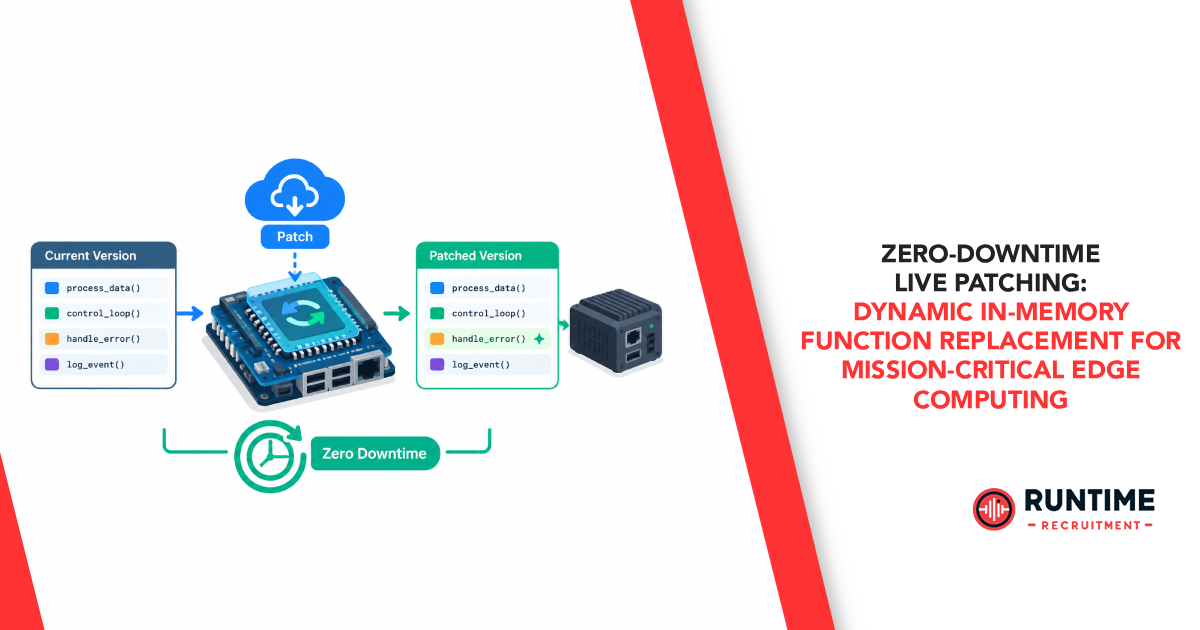
In autonomous robotics, automotive control units, grid-scale energy controllers, and subsea industrial gateways, system downtime carries high financial, operational, or safety consequences. When a security vulnerability (such as a buffer overflow in a network stack) or a critical edge logic bug is identified in a deployed MCU or edge node, the traditional remedy has been Over-The-Air (OTA) full firmware image updates.
However, traditional full-image OTA updates suffer from severe operational constraints:
Forced System Downtime: Flashing dual-bank flash memory or resetting the microcontroller requires a full system reboot, interrupting real-time control loops and sensor polling.
Loss of Volatile State: Rebooting flushes SRAM, wiping transient calibration data, active TCP connections, task queues, and sensor fusion states unless complex serialization routines exist.
Physical Wear & Power Risks: High-frequency flash erase/write cycles accelerate NOR/NAND wear and introduce power-loss vulnerability windows during write operations.
Zero-Downtime Live Patching — specifically dynamic in-memory function replacement — bypasses these limitations entirely. By modifying running machine code directly in memory or re-routing function execution at runtime, embedded engineers can hot-fix bugs, patch vulnerabilities, and update business logic in sub-millisecond timeframes without resetting the RTOS scheduler or interrupting real-time control loops.
1. Core Architecture: How Dynamic In-Memory Function Patching Works
Live patching at the embedded level differs fundamentally from desktop or cloud hot-swapping. While Linux-based edge nodes can leverage kpatch or ftrace redirection mechanisms, resource-constrained microcontroller (MCU) architectures running bare-metal C or Real-Time Operating Systems (RTOS) like FreeRTOS, Zephyr, or VxWorks require direct binary-level manipulation.
At its core, dynamic function replacement replaces or redirects an existing, buggy function (func_old) to a newly loaded, patched function (func_new) staged in executable RAM (SRAM) or reserved flash space.
Two primary paradigms dominate embedded live patching:
Indirect Function Pointer Redirection
The simplest and safest model utilizes Function Pointer Tables (similar to virtual method tables). Instead of calling func_old() directly via a static branch instruction (BL in ARM assembly), all calls to subsystem functions are routed through global function pointers stored in RAM.
Mechanism: To update the function, the patch manager writes func_new’s memory address into the pointer table via an atomic pointer swap.
Pros: Highly predictable, architecture-agnostic, and requires no runtime assembly modifications.
Cons: Incurs execution overhead (an extra memory dereference per call) and prevents the compiler from performing aggressive cross-function inline optimizations.
Binary Instruction Hooking (Trampolines)
When code is compiled with direct branch instructions, function pointer tables are unavailable. In this scenario, the patch engine injects a trampoline directly into the prologue of func_old.
Mechanism: The first 4 to 8 bytes of func_old’s machine code are overwritten with an unconditional branch instruction targeting func_new.
Pros: Operates on pre-existing binary images without architectural redesign or indirect call performance penalties during normal execution.
Cons: Demands precise binary patch generation, assembly-level architecture manipulation, cache maintenance, and thread safety enforcement.
2. Execution Mechanics: Injected Trampolines and Instruction Overwrites
To understand binary instruction hooking, consider an ARM Cortex-M architecture executing Thumb-2 instructions. Replacing a target function at runtime requires executing a sequence of hardware-level modifications:
Step 1: Generating the Relocatable Patch Payload
The updated source code for func_new must be compiled as position-independent code (using -fPIC or toolchain-specific position-independent options). This ensures relative jumps, literal pools, and global variable offsets resolve correctly regardless of where func_new is staged in SRAM or auxiliary Flash.
Step 2: Staging Payload in Executable Memory
The patch payload is transmitted via the primary field bus (e.g., CAN, Ethernet, Cellular MQTT) and validated using cryptographic signatures (e.g., Ed25519) and CRC checksums. The patch loader writes func_new into an allocated block of SRAM or flash memory marked as executable.
Step 3: Overwriting Function Prologues
To redirect callers from func_old to func_new, the patch engine modifies func_old’s initial instructions. On ARM Cortex-M, this typically involves inserting an absolute jump sequence:
LDR PC, [PC, #-4] ; Load PC directly with target address
.word 0x20008100 ; Address of func_new staged in SRAM
Alternatively, if func_new resides within relative branch range (+/- 16MB), a 32-bit B.W (Unconditional Branch) instruction can be patched directly into the entry address.
3. Hardware Hazards: Pipeline Flushes, Cache Coherency, and MPU Configuration
Modifying code in memory while a CPU actively fetches and executes instructions introduces severe hardware race conditions. Executing live updates without accounting for memory protection, pipeline states, and cache architecture will reliably trigger HardFaults, bus errors, or lockups.
Memory Protection Unit (MPU) Re-Configuration
Modern embedded processors enforce Write XOR Execute (W^X) memory safety rules via the MPU to prevent code injection exploits.
Flash regions containing func_old are configured as Read-Only / Executable (RO-X).
SRAM regions where func_new is staged are configured as Read-Write / Non-Executable (RW-NX).
To execute a live patch:
The patch manager temporarily reconfigures the target MPU region to allow Writes (RW-X).
Overwrites the trampoline bytes or writes func_new code into RAM.
Re-locks the MPU region back to Read-Only / Executable (RO-X) to maintain security guards.
Pipeline Hazards and Instruction Prefetch
Pipelined architectures (e.g., 3-stage or 5-stage pipelines in ARM Cortex-M4/M7/M33, RISC-V RV32G) prefetch and decode instructions several clock cycles ahead of execution. If the patch engine modifies the bytes of func_old while another thread or interrupt handler fetches instructions from that memory region, the core will execute a corrupted mix of stale and patched instructions.
To prevent pipeline corruption:
Target memory writes must be atomic (e.g., updating a single 32-bit word containing the branch instruction).
The patch engine must execute a pipeline flush instruction immediately following the memory write. On ARM architectures, the Instruction Synchronization Barrier (ISB) instruction forces the processor to clear its prefetch pipeline buffer and re-fetch instructions from memory.
Cache Coherency (Data vs. Instruction Caches)
High-performance edge processors (e.g., ARM Cortex-A series, ARM Cortex-R52, or Cortex-M7) feature split Harvard cache architectures: a Data Cache (D-Cache) and an Instruction Cache (I-Cache).
When func_new is written or func_old is modified:
The CPU writes patch bytes through the D-Cache to physical RAM.
The I-Cache remains unaware of this write and retains stale, pre-patched instructions.
Subsequent function calls execute stale code from the I-Cache, causing non-deterministic crashes.
To maintain cache coherency, embedded developers must execute a mandatory cache synchronization sequence:
Clean D-Cache: Force dirty D-Cache lines containing modified code back to physical RAM (DCCMVAC).
Data Synchronization Barrier (DSB): Wait for all memory access write buffers to complete.
Invalidate I-Cache: Clear I-Cache lines corresponding to patched memory addresses (ICIMVAU), forcing future fetches to pull fresh code from main memory.
Instruction Synchronization Barrier (ISB): Flush the execution pipeline.
4. Thread Safety and Task Consistency: Preventing State Corruption
Hardware mechanics represent only half the live patching challenge; software state consistency is equally vital. If an active RTOS task is currently executing inside func_old when its prologue is overwritten with a jump instruction, severe stack corruption or execution flow divergence will occur.
Stop-the-World vs. Quiescent State Inspection
Two main strategies ensure thread safety during live patch injection:
Stop-the-World (Global Scheduler Suspension):
The patch manager enters a critical section, disabling global interrupts (__disable_irq()) or suspending the RTOS task scheduler (vTaskSuspendAll()).
Limitation: Disabling interrupts breaks hard real-time guarantees, potentially causing motor control loops or high-speed communication interfaces to miss critical deadlines.
2. Quiescent State Inspection (Stack Scanning):
Rather than halting the operating system, the patch loader inspects the stack frame of every active RTOS task.
The loader verifies that no task stack contains return addresses (LR register values) pointing inside the address range of func_old or its call hierarchy.
If a task is detected executing inside func_old, the patch loader defers patching until the task exits the function and reaches a designated “quiescent state” (e.g., an idle loop or block waiting on an RTOS queue).
Handling Function Interface Constraints
When designing live patches, function signatures must remain strictly compatible with original caller assumptions:
Stack Alignment & Frame Pointer Compatibility: The compiler-generated stack frame layout for func_new must match parameters passed by func_old callers according to the target ABI (e.g., AAPCS for ARM).
Global Data Structure Constraints: Adding new fields to existing global structs used by unpatched modules will break offset assumptions across the rest of the codebase. Instead, extended dynamic state should be maintained in separate, dynamically allocated patch metadata structures.
5. Verification, Watchdogs, and Atomic Rollback Strategies
In mission-critical edge deployments, any automated system modification carries inherent risks. An edge device operating at a remote substation or inside an autonomous vehicle must be capable of self-healing if a patch exhibits runtime instability.
Atomic State Rollback
If func_new encounters an unhandled exception, triggers an MPU violation, or fails an internal post-patch assertion test, the system must perform an instant, deterministic rollback:
Function Pointer Redirection: Rollback requires an atomic swap of the function pointer back to func_old’s address.
Instruction Hooking: The original 4 to 8 bytes saved prior to overwriting func_old’s prologue are restored into func_old, followed by D-Cache clean, I-Cache invalidation, and pipeline ISB flushing.
Dual-Stage Watchdog Supervision
To protect against logic hangs or deadlocks inside func_new:
Software Patch Watchdog: Before executing func_new, a dedicated timer monitor is armed. func_new must complete execution and refresh the timer.
Hardware Watchdog Timer (WDT): If func_new causes an unrecoverable CPU lockup, the hardware WDT expires, rebooting the device into a safe bootloader recovery partition that automatically blacklists the faulty patch binary.
6. Firmware Update Methodology Comparison
The following matrix illustrates how live patching compares to conventional edge update paradigms:

7. Real-World Implementation: ARM Cortex-M Trampoline Hooking Sequence
The following C implementation demonstrates the core steps required to perform an atomic, cache-safe in-memory function replacement on an ARM Cortex-M microcontroller running an RTOS environment:

8. Engineering Resilient Edge Infrastructure
As edge computing nodes assume direct control over critical industrial, automotive, and energy infrastructure, the traditional “reboot-to-update” model is rapidly becoming an operational liability. Incorporating zero-downtime live patching into your embedded software pipeline transforms security and bug mitigation. Vulnerability response shifts from multi-week maintenance scheduling to real-time, deterministic hot fixes.
By mastering trampoline mechanics, cache coherency protocols, MPU reconfigurations, and task consistency checks, embedded systems engineers can build resilient, self-healing edge architectures capable of years of continuous uptime without losing state or missing real-time deadlines.
Need Embedded Engineering Talent for Mission-Critical Projects?
Building deterministic, high-reliability edge systems requires elite engineering talent skilled in RTOS internals, low-level assembly, and advanced firmware architecture.
Connect with RunTime Recruitment—your specialist recruitment partner for sourcing top-tier embedded systems, firmware, and electronics engineering professionals.