
Pin-Compatible, Code-Incompatible: Rapidly Swapping MCUs When Supply Chains Disrupt
25 September 2026 · Lance Harvie
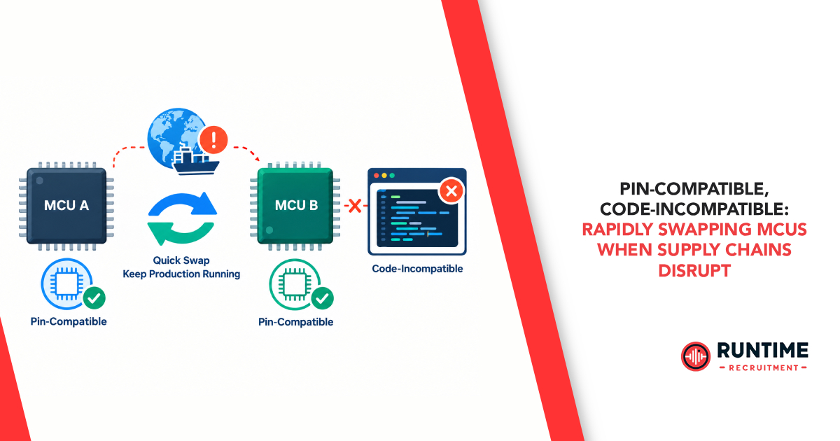
The embedded engineering landscape has experienced unprecedented supply chain volatility over recent years. Component lead times expanding beyond 52 weeks, sudden end-of-life (EOL) notifications, and cost spikes have turned component selection into a high-stakes gamble. When a primary microcontroller unit (MCU) becomes completely unobtainable, procurement teams frantically search for secondary sources.
Often, the search yields what appears to be a drop-in solution: a microcontroller boasting the exact same physical package (e.g., LQFP-64 or QFN-48), identical pin assignments, and even the same core architecture (such as an Arm Cortex-M4).
However, senior embedded engineers know the harsh reality: pin-compatible hardware is almost never code-compatible software.
Plugging a pin-compatible alternative onto an existing PCB footprint and flashing the legacy firmware image typically results in absolute silence, hard faults, or unpredictable system crashes. Bridging the gap between physical pin compatibility and software execution requires a deep understanding of low-level silicon differences, defensive firmware architecture, and a structured migration methodology.
The Hardware Reality Beneath “Pin Compatibility”
Before addressing software, firmware engineers must recognize that physical drop-in compatibility at the board layout level does not guarantee electrical equivalence. Even when two MCUs share identical pinouts and package footprints, silicon revision differences, process node changes, or vendor implementation choices introduce electrical variations.

1. Power Supply Topology and Internal Regulators
Microcontrollers often require external decoupling networks, internal Low-Dropout (LDO) regulators, or switching regulators (DC-DC buck converters) to power the core logic.
VCAP / VDDCORE Pins: One MCU might integrate an internal LDO requiring a single 2.2 µF capacitor on a specific pin, while a pin-compatible competitor requires an external core voltage or a dual-capacitor network. Connecting the wrong decoupling capacitance can lead to internal regulator instability, brownout resets, or severe noise injection.
Power-On Reset (POR) Thresholds: Voltage monitoring circuits, brownout detector (BOD) trigger levels, and startup timing profiles vary. An alternative MCU might hold the system in reset longer or require a steeper power rail ramp rate dV/dt to boot reliably.
2. Output Driver Slew Rates and EMI Compliance
Fabrication process nodes vary drastically across semiconductor foundries. A drop-in replacement fabricated on a smaller process node may feature output transistors with significantly faster rise and fall times.
High-speed switching edges increase high-frequency electromagnetic interference (EMI) and signal ringing on high-speed traces (e.g., SPI, high-speed PWM, or external memory buses).
If the legacy PCB design relied on the slower slew rates of the original MCU to pass compliance, swapping to a faster silicon revision without adjusting internal GPIO drive strength registers can cause the product to fail radiated emissions testing.
3. Clock Tree Dynamics and Crystal Oscillators
While both chips may support external high-speed crystals (HSE), their internal Pierce oscillator driver circuits often differ:
Transconductance g_m: Variations in internal oscillator drive capacity can result in a failure to oscillate with the existing crystal and load capacitor selection, or conversely, overdrive and damage delicate low-power crystals.
Phase-Locked Loop (PLL) Architecture: Multipliers, dividers, and lock-time requirements differ substantially. Firmware that assumes a 10 ms PLL lock-time might execute code before the core clock stabilizes on the replacement MCU, precipitating immediate CPU hard faults.
The Software Chasm: Why Code Fails on Equivalent Silicon
When two microcontrollers share the exact same instruction set architecture (ISA) — for instance, an Arm Cortex-M core — code compiled for one chip will physically execute instructions on the other. However, the peripherals surrounding that core are completely proprietary to each semiconductor vendor.

1. Register Maps and Memory Layout Discrepancies
Even within a single vendor’s product portfolio, moving between MCU families (e.g., from an Arm Cortex-M0+ to a Cortex-M4, or from an STM32F4 to an STM32G4) changes register offset maps. Accessing a USART control register on MCU A might overwrite an unmapped or completely different control register on MCU B.
Linker scripts (.ld or .icf) must be overhauled. Flash wait-state configurations (FLASH_ACR registers) must match the new chip’s access speed relative to core frequency. Failing to set adequate Flash wait-states before ramping up clock speeds causes immediate instruction fetch corruption.
2. Peripheral Architecture Divergence
Direct Memory Access (DMA)
DMA engine designs vary wildly across vendors. MCU A might use a stream-based DMA architecture with fixed hardware request channels, while MCU B uses a flexible routing matrix (e.g., DMAMUX) or linked-list descriptors (scatter-gather DMA).
Circular buffer management for UART reception or audio playback requires completely different interrupt handling and flag-clearing sequences.
Bus matrix arbitration priorities between CPU and DMA transfers differ, leading to unexpected memory access latency or DMA starved conditions under heavy CPU load.
Advanced Timers and Interrupts
Timers are among the most complex peripherals on modern MCUs.
PWM generation routines that depend on specific center-aligned counting modes, break inputs, or complementary output control cannot be mapped 1:1 between vendors.
Interrupt priorities and vector table allocations change. Shared interrupt vectors (where UART, I2C, and Timers share a single Nested Vectored Interrupt Controller line) require complex status-flag checking in the ISR to route execution correctly.
Architectural Strategies for Swap Resilience
To minimize downtime when supply chains force an emergency MCU swap, engineering teams must transition from vendor-dependent coding to vendor-agnostic firmware architectures before crisis hits.
1. The Layered Firmware Abstraction Pattern
Relying solely on vendor-supplied Hardware Abstraction Layers (HALs) — such as STM32CubeHAL, NXP MCUXpresso SDK, or Microchip Harmony — creates pseudo-lock-in. While these libraries abstract raw registers, their APIs are entirely proprietary. Swapping vendors means rewriting 80% of your application’s device-driver interactions.
Instead, implement a strict three-tier software architecture:

Application Layer
Contains pure business logic, control algorithms, state machines, and data processing routines. This layer contains zero references to MCU-specific header files (e.g., #include “stm32f4xx.h” is strictly forbidden).
Driver Abstraction Layer (DAL)
Defines standardized, application-centric interfaces. For instance, rather than calling HAL_UART_Transmit_IT(&huart1, data, len), the application invokes sys_telemetry_transmit(data, len).
Hardware Adapters (BSP)
Implements the DAL interface for specific hardware targets. Switching MCUs simply requires swapping the compiled adapter implementation module (e.g., uart_adapter_stm32.c to uart_adapter_gd32.c or uart_adapter_nxp.c) in the build system, leaving the upper application codebase 100% untouched.
2. Hardware Design Strategies for Drop-In Resilience
Designing PCBs with component substitution in mind significantly reduces hardware spin iterations when silicon shortages occur:
Universal Pad Layouts (Dual Footprints): Design PCB footprints that accommodate two package sizes on the same physical space (e.g., overlapping QFN and TQFP pads for identical pinouts across vendors).
Solder Jumpers for Power Configuration: Include 0-ohm resistor pads or solder bridges on VCAP, VREFN, and BOOT pins. This permits reconfiguring power paths, internal regulator caps, or boot mode selections without laying out a brand-new PCB revision.
Normalize Alternate Functions During Schematic Capture: When selecting pin assignments for the primary MCU, cross-reference candidate alternate MCUs. Route SPI, I2C, and UART signals to pins that serve the exact same peripheral roles across all candidate chips.
The Rapid MCU Migration Playbook
When an emergency swap is triggered, engineering teams need a systematic protocol to bring up the replacement silicon efficiently and safely.

Phase 1: Electrical & Pinmux Audit
Compare Pin Matrices Side-by-Side: Inspect power pins, ground planes, analog references (V_REF+), and boot-configuration pins BOOT0/BOOT1.
Review Errata Sheets Immediately: Silicon bugs on the replacement chip may invalidate features your application relies on (e.g., known I2C bus lockup conditions or broken DMA burst modes).
Verify Voltage Tolerances: Check whether input pins on the replacement MCU remain 5V-tolerant if interfacing with legacy 5V sensors.
Phase 2: Linker and Memory Map Realignment
Update Flash and RAM Boundaries: Configure the build system’s linker script with exact memory bank origins and sizes.
Reserve Bootloader Regions: Ensure vector table remapping offsets (SCB->VTOR) correctly point to the application start address if using an in-field bootloader.
Phase 3: Clock Tree and Power Architecture Bring-Up
Write Bare-Metal Clock Init: Before initializing complex peripherals, write a minimal bring-up routine that configures internal LDOs, enables the oscillator, locks the PLL, and sets Flash wait-states.
Verify Frequency via MCO: Route the internal system clock to a Microcontroller Clock Output (MCO) pin and measure it with an oscilloscope or frequency counter to confirm the CPU is executing at the intended clock rate.
Phase 4: Driver Adapter Porting
System Tick & Timers: Initialize system tick timers (SysTick) and basic timebase generators first.
Serial Debug Console: Port the primary UART logging driver immediately. Real-time serial logging is essential for diagnosing hard faults during subsequent peripheral bring-up.
Bus Drivers (SPI/I2C): Port synchronous communication interfaces and validate signal timing, phase, and edge polarities with a logic analyzer.
Asynchronous & Complex Peripherals: Port DMA controllers, ADC sampling loops, and advanced motor-control PWM drivers last.
Phase 5: System Validation and Compliance Re-Testing
Stress-Test Interrupt Latency & DMA Throughput: Run worst-case execution time (WCET) analyses to confirm the replacement silicon satisfies real-time requirements under heavy interrupt load.
Thermal & Environmental Testing: Verify oscillator startup and internal regulator stability across extended operating temperature ranges.
EMI Pre-Compliance Scan: Conduct near-field probe measurements over high-speed buses to ensure changes in GPIO slew rates haven’t compromised the product’s EMC profile.
Building a Future-Proof Embedded Workflow
Pin-compatible microcontrollers provide a vital lifeline when global supply chains disrupt production schedules. However, relying on physical pin compatibility alone is a dangerous trap. Real supply chain resilience demands a firmware architecture decoupled from vendor-specific libraries, a hardware design strategy that anticipates component variations, and a disciplined porting methodology.
By treating hardware-level abstraction as a core architectural requirement rather than an afterthought, engineering organizations can pivot between microcontroller suppliers in days rather than months — turning potential supply chain catastrophes into seamless technical transitions.
Need expert embedded talent to navigate complex hardware redesigns or firmware migrations? Connect with RunTime Recruitment to source specialized embedded systems engineers and technical leaders who keep your engineering projects moving forward, no matter the supply chain conditions.