
Guaranteeing Hard Real-Time Deadlines: Worst-Case Execution Time (WCET) Analysis for Multi-Core MCUs
23 September 2026 · Lance Harvie
1. Introduction: The Multi-Core Determinism Paradox
In hard real-time embedded systems — such as automotive safety domains (ISO 26262 ASIL-D), industrial motion control (IEC 61508 SIL-3), aerospace avionics (DO-178C DAL-A), and medical devices — a system failure is not defined merely by producing an incorrect output value. A failure occurs if a correct value is delivered a single clock cycle past its strict, deterministic deadline.
For decades, real-time embedded firmware developers relied on single-core microcontrollers (e.g., ARM Cortex-M3/M4, Classic AUTOSAR targets). Single-core topologies provided a predictable, straightforward execution environment: code executed sequentially, interrupts preempted tasks according to fixed priorities, and instruction timing was largely deterministic or boundable through straightforward static analysis.
However, modern embedded systems demand unprecedented processing throughput. Requirements for advanced signal processing, machine learning at the edge, complex sensor fusion, and unified domain controllers have pushed silicon vendors to transition to multi-core microcontrollers (MCUs). Architectures like the dual-core ARM Cortex-M7/M4 (e.g., STMicroelectronics STM32H7), multi-core Cortex-R52 automotive processors, Infineon AURIX TC3xx/TC4xx TriCore devices, NXP S32K3, and multi-hart RISC-V platforms are now standard in high-performance embedded engineering.
This transition introduces the Multi-Core Determinism Paradox: while multi-core processing vastly increases peak theoretical compute performance, it severely compromises execution predictability. When multiple processing cores concurrently access shared hardware resources — such as system buses, crossbar interconnects, shared SRAM, flash memory controllers, and peripheral blocks — they introduce non-deterministic contention delays.
In a hard real-time multi-core environment, relying on Average-Case Execution Time (ACET) or empirical benchmarking using logic analyzers, digital storage oscilloscopes, or internal timers is dangerous. An empirical test vector can demonstrate that a task executed in 12 microseconds across ten million test iterations; however, it cannot prove that a specific, rare combination of inter-core bus contention, cache invalidation, and DMA preemption will not push that execution time to 45 microseconds in the field, breaching a critical hard real-time deadline.
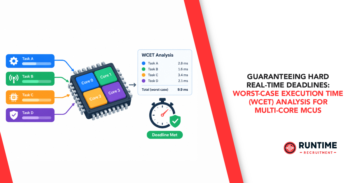
To guarantee hard real-time performance on multi-core MCUs, embedded engineers must perform formal Worst-Case Execution Time (WCET) Analysis. WCET represents the absolute upper bound on the time a software task takes to execute on a specific hardware platform under any valid input state and worst-case architectural interference.
2. Microarchitectural Sources of Non-Determinism in Multi-Core MCUs
To bound execution time, firmware engineers must first understand the hardware physical mechanisms within multi-core microcontrollers that cause timing variance. In a single-core MCU, instruction execution variability is primarily driven by branch mispredictions, pipeline stalls, and interrupt latency. In a multi-core MCU, cross-core interference mechanisms compound these factors significantly.

Shared Bus and Crossbar Interconnect Contention
Multi-core MCUs employ multi-layer Advanced High-performance Bus (AHB) or Advanced eXtensible Interface (AXI) crossbar matrices to interconnect core bus masters with memory slaves. When Core 0 and Core 1 attempt to issue memory transactions (read/write) to the same target slave or memory bank simultaneously, the bus hardware arbiter must grant access to one core while stalling the other.
Arbitration policies vary by vendor and configuration:
Round-Robin Arbitration: Ensures fairness, but introduces a worst-case stall penalty equal to the maximum transaction duration of all competing cores multiplied by the number of cores.
Fixed Priority Arbitration: Guarantees low latency for the highest-priority core, but causes dynamic, unbounded latency tails for lower-priority cores subject to starvation.
Memory Hierarchy Interference and Cache Coherency
Modern high-performance MCUs utilize L1 instruction (I-Cache) and data (D-Cache) caches to bridge the gap between fast CPU clock rates and slower embedded flash/SRAM access times. In a multi-core topology, caches introduce severe non-determinism:
Shared Cache Thrashing: If cores share an L2 cache, Core 1 may evict cache lines containing critical code or lookup tables actively used by Core 0, converting subsequent single-cycle cache hits into multi-cycle memory fetching stalls.
Cache Coherency Overhead: When cores share data across memory spaces, hardware cache coherency protocols (e.g., MESI or MOESI snooping logic) enforce consistency. Snoop requests and cache line invalidation signals saturate the internal interconnect, introducing core execution pipeline stalls.
Write Buffers and Non-Blocking Caches: Memory write-buffers defer bus transactions. If a write-buffer fills during sustained memory accesses, execution pipelines stall until the buffer flushes to physical RAM.
Hardware Lock Contention and Atomic Operations
Inter-core synchronization relies on atomic primitives, such as LDREX/STREX in ARM architectures or hardware semaphore controllers. When multiple cores execute synchronization loops (spinlocks) waiting for a shared mutex, exclusive monitor hardware invalidates local core states upon access. This generates bus traffic storms and delays pipeline completion for all participating cores.
Peripheral and DMA Crosstalk
Cores do not operate in isolation from system I/O. Autonomous high-speed Direct Memory Access (DMA) engines (e.g., streaming Ethernet frames, CAN-FD message buffers, or high-speed ADC samples) act as secondary bus masters. DMA memory transfers contend directly with CPU cores for SRAM bank access, introducing instruction execution jitter that varies depending on external data traffic.
3. WCET Analysis Methodologies: Static, Dynamic, and Hybrid
Determining a provable WCET bound on multi-core MCUs requires rigorous analytical frameworks. Embedded engineers utilize three primary methodologies to calculate WCET: Static Analysis, Measurement-Based Dynamic Analysis, and Hybrid Analysis.

1. Static WCET Analysis (Abstract Interpretation & IPET)
Static analysis evaluates compiled machine binaries directly without executing code on physical target hardware. It guarantees a mathematically sound upper bound by analyzing all possible execution paths and microarchitectural states.
Static analysis tools (such as AbsInt aiT, BoundT, or Rapita Systems) operate in three distinct phases:
Control Flow Graph (CFG) Reconstruction: The tool parses the compiled binary ELF file, reconstructing the assembly-level control flow graph to identify loops, conditional branches, function calls, and recursion. Note: Source-level analysis is insufficient because compiler optimizations (e.g., loop unrolling, instruction reordering, function inlining, vectorization) significantly alter instruction execution paths.
Microarchitectural Modeling: The tool simulates the MCU’s internal pipeline, branch predictors, cache structures, and bus interfaces using Abstract Interpretation (AI). It computes abstract cache states (ACS) to classify memory accesses as Always Hit (AH), Always Miss (AM), or First Miss (FM).
Implicit Path Enumeration Technique (IPET): The CFG structure and microarchitectural timing bounds are mapped into an Integer Linear Programming (ILP) system. The target execution time TWCET is represented as:

Where ci is the execution time cost of basic block i, and xi is the execution count of basic block i along the execution path. The ILP solver calculates the theoretical worst-case path through the graph.
The Multi-Core Challenge for Static Analysis: Static modeling of multi-core microarchitectures faces severe state-space explosion. To maintain mathematical soundness without modeling every cycle-level state of neighboring cores, static tools must assume worst-case bus arbitration delays for every shared memory access. This often yields overly pessimistic WCET bounds (e.g., calculating a WCET 300% higher than physical reality), forcing engineers to over-spec hardware.
2. Measurement-Based / Dynamic Execution Time Analysis (MBETA)
Dynamic analysis determines execution timing empirically by running software on physical silicon or cycle-accurate emulators under test conditions.
Methods include:
Hardware Tracing: Utilizing non-intrusive trace hardware like ARM CoreSight ETM (Embedded Trace Macrocell), Nexus trace, or Infineon MCDS to capture cycle-accurate instruction timing logs over high-speed trace pins (e.g., Lauterbach Trace32).
GPIO Toggling & Internal Timers: Toggling hardware pins observed via high-bandwidth oscilloscopes or reading high-resolution hardware cycle counters (e.g., ARM Cortex DWT->CYCCNT).
The Flaw of Pure Dynamic Analysis: Dynamic measurement records the Maximum Observed Execution Time (MOET) under specific test conditions. However, MOET is inherently unprovable for hard real-time systems. In complex multi-core MCUs, the probability of triggering the worst-case alignment of pipeline stalls, cross-core bus contention, cache evictions, and interrupt handling simultaneously via functional test vectors approaches zero. Relying on MOET+20% safety margin is an unreliable, unvalidated design risk for safety-critical firmware.
3. Hybrid WCET Analysis
Hybrid analysis combines the strengths of static and dynamic approaches. Static tools build the assembly-level Control Flow Graph (CFG) to map all structural paths, while real-time execution measurements are collected for individual basic blocks or small, deterministic code segments using non-intrusive trace hardware.
The hybrid engine assigns measured worst-case execution bounds to the individual basic blocks, then utilizes IPET to aggregate these values along the worst-case path. Hybrid analysis avoids microarchitectural modeling complexity for complex multi-core interconnects while maintaining structural path bounds.
4. Architectural Mitigation Strategies: Designing for Multi-Core Determinism
Rather than attempting to perform complex static analysis on an unconstrained, highly non-deterministic multi-core MCU system, embedded software architects must apply hardware-enforced isolation patterns. By designing for determinism at the system level, engineers bound inter-core interference penalties before performing WCET analysis.

1. Memory Partitioning: Tightly Coupled Memories (TCM)
The most effective strategy for guaranteeing WCET on multi-core MCUs is bypassing shared bus interconnects entirely for critical execution loops.
Modern real-time cores (e.g., ARM Cortex-R52, Cortex-M7) provide Tightly Coupled Memories:
ITCM (Instruction TCM): Dedicated local memory mapped directly to the core’s instruction pipeline.
DTCM (Data TCM): Dedicated local memory mapped directly to the core’s load/store pipeline.
By locating hard real-time Interrupt Service Routines (ISRs), inner control loops, and critical stack frames inside core-private ITCM/DTCM, execution time becomes invariant to activity on adjacent cores. Memory access latency drops to a deterministic single cycle, eliminating crossbar bus arbitration stalls.
2. Cache Partitioning and Way-Locking
When code size exceeds local TCM capacity and must execute from cached memory, engineers should implement Cache Way-Locking.
Most multi-way set-associative caches allow developers to configure control registers to “lock” specific cache ways:
Configuration Example: On a 4-way set-associative cache, lock Ways 0 and 1 exclusively for Core 0’s hard real-time safety critical tasks.
Result: Cores 1 and 2 are restricted to allocating and evicting cache lines within Ways 2 and 3. This hardware firewall completely prevents neighboring cores from evicting critical code/data lines assigned to Core 0, bounding cache miss rates statically.
3. Asymmetric Multiprocessing (AMP) vs. Symmetric Multiprocessing (SMP)
For hard real-time systems, favor an Asymmetric Multiprocessing (AMP) operating model over Symmetric Multiprocessing (SMP):
SMP Pitfalls: An SMP RTOS dynamically schedules threads across any available core at runtime. This causes thread migration, dynamic cache invalidation, and unpredictable cross-core lock contention, rendering WCET calculation virtually impossible.
AMP Strategy: Assign dedicated tasks statically to explicit cores. Core 0 executes the safety-critical hard real-time control loop (e.g., motor vector control at 20 kHz); Core 1 handles communication stacks (e.g., CANopen, Ethernet/IP) and diagnostics. Core affinity is locked at compile/configuration time.
4. Predictable Execution Models (PREM) / Memory-Centric Scheduling
In advanced systems, software architects adopt the Predictable Execution Model (PREM). Tasks are restructured into two explicit execution phases:
Memory Phase (Prefetch): The core fetches all required data and code blocks from shared system flash/RAM into local scratchpad memory or TCM. This phase interacts with shared buses under strict time-triggered schedules.
Execution Phase (Compute): The core executes exclusively out of its local scratchpad memory with zero shared-memory access.
Because the execution phase guarantees zero bus interference, its WCET equals that of an isolated single-core system. Inter-core communication is scheduled in phase-shifted time slots (Time-Triggered Architecture), completely preventing bus collisions across cores.
5. A Practical Workflow for WCET Verification in Multi-Core Projects
To successfully qualify multi-core embedded software for hard real-time deployment, firmware teams should integrate the following step-by-step WCET analysis workflow into their development lifecycle:

Step 1: Enforce Deterministic Code Design Standards
Before running WCET tools, write WCET-friendly software:
Enforce Upper Bounds on All Loops: Avoid while(cond) loops dependent on dynamic peripheral state without an explicit hardware cycle timeout counter. Annotate loops with pragmas (e.g., #pragma loop_bound(max=16)) to inform static analysis engines.
Eliminate Dynamic Memory Allocation: Banish malloc() and free(). Use statically allocated arrays and fixed-size block memory pools to eliminate heap fragmentation latency.
Avoid Function Pointer Indirection: Virtual function tables and heavy function pointer usage obscure the Control Flow Graph. Use static dispatch where possible.
Structure Inter-Core Queues for Zero Locks: Implement single-producer, single-consumer lock-free ring buffers using atomic memory primitives instead of blocking RTOS mutexes.
Step 2: Establish Microarchitectural Isolation
Map critical software assets to deterministic hardware regions within your linker script (.ld / .icf):
Place interrupt vectors, critical RTOS kernel routines, and high-frequency control loops into ITCM.
Place ISR stack spaces and real-time state variables into DTCM.
Configure the MCU’s Memory Protection Unit (MPU) to trap unauthorized cross-region memory accesses.
Step 3: Quantify Inter-Core Contention Margins
When tasks must access shared system SRAM across the AXI crossbar, parameterize the worst-case bus delay. Calculate the maximum crossbar transaction latency by evaluating:
LatencyBusMax=(Ncores−1)⋅StallCyclesTransaction+LatencyDMA
Set the static analyzer’s hardware configuration file to apply this worst-case penalty to every uncached or shared memory access instruction.
Step 4: Perform Hybrid/Static Toolchain Verification
Parse the compiled .elf binary through your static or hybrid WCET toolchain.
Inspect the reconstructed Control Flow Graph for worst-case execution path visualization.
Identify the Critical Path: evaluate whether the highest WCET contributions stem from loop iterations, cache misses, or bus contention stalls.
Compare the calculated TWCET against your system deadline limit (TDeadline). Ensure your engineering design margin satisfies:
TWCET+TISR_Overhead+TContextSwitch≤TDeadline
Step 5: Automate WCET Checks in Continuous Integration (CI)
Verification is not a one-time activity at the end of a project. Integrate static WCET analysis or trace-based timing verification scripts into your build pipeline (e.g., GitLab CI, Jenkins, GitHub Actions).
Set build gates that automatically flag commits if a firmware pull request increases the calculated WCET of a hard real-time task beyond its allocated execution budget.
6. Conclusion
Guaranteeing hard real-time deadlines on multi-core MCUs requires a fundamental shift in how embedded software engineers design, implement, and verify firmware. As hardware topologies move toward complex multi-core, heterogeneous architectures, empirical bench testing alone can no longer guarantee safety.
By understanding the microarchitectural sources of cross-core non-determinism, enforcing hardware isolation through TCM and cache partitioning, establishing AMP software patterns, and utilizing formal static/hybrid WCET analysis workflows, firmware developers can harness multi-core performance while guaranteeing absolute real-time determinism.
Accelerate Your Embedded Engineering Career and Team Growth
Building safety-critical multi-core embedded systems requires exceptional, highly specialized engineering talent.
Whether you are an embedded software engineer looking for your next career challenge in safety-critical systems, or an engineering manager searching for top-tier firmware, RTOS, and hardware talent, connect with RunTime Recruitment. As specialized recruiters in the embedded systems, firmware, and electronics design industries, we match high-caliber engineering talent with industry-leading technology companies worldwide.
Contact RunTime Recruitment Today to discuss your hiring requirements or explore specialist embedded engineering opportunities.