
Passive NFC Field Diagnostics: Reading Error Logs and Extracting Telemetry from Fully Powered-Down Devices
21 August 2026 · Lance Harvie
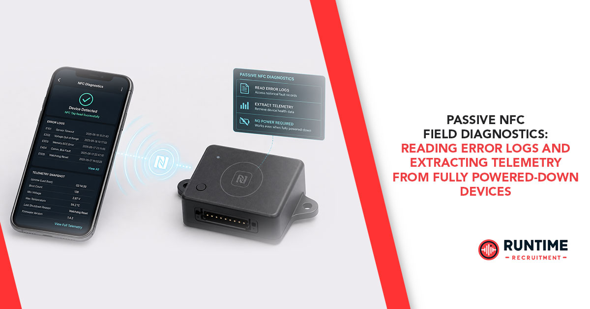
Every embedded engineer who has deployed hardware into harsh industrial, remote, or outdoor environments knows the dread of receiving a "bricked" return merchandise authorization (RMA) unit. The device arrives on the bench in a completely unresponsive state: the power supply rail is dead, the main lithium battery is depleted or chemically locked, status LEDs remain dark, and the primary microcontroller (MCU) refuses to boot.
To make matters worse, modern industrial sensors, medical devices, smart meters, and automotive modules are frequently rated IP68 or fully encapsulated in potting compound. Diagnosing the failure using traditional methods—cracking open the sealed enclosure, soldering microscopic fly-wires to debug pads, and probing JTAG or UART interfaces—is destructive, labor-intensive, and invalidates the failure analysis context.
What if you could diagnose a completely unpowered device without opening its case, plugging in a single wire, or supplying external system power?
By leveraging dynamic (dual-interface) NFC tag ICs, embedded system engineers can build a zero-power "black box" logging architecture. This capability allows field technicians and RMA engineers to extract critical error logs, stack dumps, sensor telemetry, and operational health history simply by tapping a smartphone or handheld terminal against a fully powered-down device.
The Architecture of Dynamic Dual-Interface NFC ICs
Standard passive NFC tags (such as those found in smart posters or stickers) are static, single-port devices containing pre-programmed EEPROM accessed exclusively over an RF link. Dynamic NFC tag ICs (such as STMicroelectronics' ST25DV series or NXP's NTAG I²C family), by contrast, feature a dual-port architecture:
Wired Contact Interface: A standard I²C or SPI bus connected directly to the host system microcontroller.
Wireless Contactless Interface: A 13.56 MHz RF interface complying with ISO/IEC 15693 or ISO/IEC 14443 standards, communicating wirelessly with NFC readers or smartphones.
At the center of a dynamic tag IC is a shared, non-volatile EEPROM array. When the main device is powered up and operating normally, the host MCU writes telemetry, runtime statistics, panic codes, and environmental data into the tag’s memory via I²C.
When the device suffers a catastrophic failure, loses power, or shuts down completely, the host MCU powers down—but the dynamic tag's EEPROM retains all stored information.
When an RF reader (such as a technician's smartphone) approaches the dead device, the magnetic field generated by the reader induces a current in the device's NFC antenna. The dynamic tag IC rectifies this RF field to power its internal digital core and transmitter, reading out the saved diagnostics from EEPROM without needing a single milliwatt from the host system’s battery or power supply.
Additionally, many dynamic NFC ICs feature an Energy Harvesting ($V_{\text{EH}}$) output pin. This pin can harvest electromagnetic energy from the active RF reader and deliver a small DC voltage (typically 1.8V to 3.3V at up to several milliamps). This harvested energy can temporarily wake an ultra-low-power host MCU or trigger onboard field detection interrupts even when the primary power rail is completely disconnected.
Designing a Zero-Power "Black Box" Memory Architecture
To implement reliable passive diagnostics, firmware engineers must treat the dynamic NFC tag's EEPROM as a high-reliability flash-black-box recorder. Relying on host internal flash or external SPI flash for last-gasp logging often fails during supply collapse due to long sector-erase delays, high programming voltages, and voltage brownouts.
1. Flash vs. Shared EEPROM
Internal MCU flash updates during a fault event carry risks. If a supply rail drops below the flash write threshold mid-page, partial writes can corrupt system sectors. EEPROM on a dynamic tag IC, powered over I²C with write times under 5 ms per page, provides a safer landing zone for rapid register dumps.
2. Firmware Logging Strategies
Rather than constantly writing to EEPROM and consuming write endurance cycles (typically 1 million cycles at 25°C), firmware should implement a dual-tier strategy:
Periodic Heartbeat & Telemetry (Interval-based): Every few minutes or hours, write cumulative stats—such as operational runtime hours, maximum internal temperature, battery state of charge, min/max supply voltages, and sensor calibration metrics.
Fault-Driven Event Logging (Interrupt-driven): When software assertions fail, hardware watchdogs trip, or brownout detection circuits activate, immediately flush an event frame.
3. Implementing the "Dying Gasp" Flush
When primary power collapses, the MCU must log its failure state before system capacitors drain completely.
+-------------------------------------------------------------------+
| Power Supply Rail Drops |
+-------------------------------------------------------------------+
|
v
+---------------------------------------------------------------------------------+
| Hardware Brownout Detector (BOD) Interrupt Trips |
+---------------------------------------------------------------------------------+
|
v
+---------------------------------------------------------------------------------+
| NMI / High-Priority ISR Locks Peripheral Execution |
+---------------------------------------------------------------------------------+
|
v
+--------------------------------------------------------------------------------------------+
| Assembly Diagnostics Capture: PC, LR, SP, Fault Registers (CFSR) |
+-------------------------------------------------------------------------------------------+
|
v
+---------------------------------------------------------------------------------------------+
| High-Speed I2C Flush (1 MHz) to Dynamic Tag EEPROM Array |
+---------------------------------------------------------------------------------------------+
|
v
+-------------------------------------------------------------------+
| System Halts / Depletes Bulk Storage Capacitors |
+-------------------------------------------------------------------+
By sizing the board’s primary bulk decoupling capacitors properly, engineers can guarantee a hold-up time of 5 to 10 milliseconds after brownout trip—more than enough time to send a 64-byte diagnostic payload over a 1 MHz Fast-Mode Plus I²C bus.
NDEF vs. Raw Sector Layout: Structuring Diagnostic Telemetry
How should dynamic tag EEPROM memory be formatted? Embedded engineers usually choose between standardized NDEF (NFC Data Exchange Format) structures and Raw Binary Sector Layouts.

The Hybrid Layout Strategy
The most effective field diagnostic implementation uses a hybrid memory layout:
Public NDEF Sector (Unprotected): Contains a standard URI or Text NDEF record. Tapping the dead device with an unmodified smartphone automatically launches a web dashboard or opens a local maintenance app, displaying basic device identity, serial number, firmware revision, and a human-readable fault summary (e.g., "Error 0x42: Battery Over-Temperature Shutdown").
Protected Diagnostics Sector (Password-Gated): Contains binary-packed fault logs, task control blocks, register snapshots (r0-r12, LR, PC, CFSR), and raw sensor history. Access to this block via RF requires authentication using 64-bit passwords or symmetric key validation supported by the tag IC.
Pass-Through / Mailbox Mode: Interactive Zero-Power Testing
While reading static logs from EEPROM solves post-mortem analysis, advanced dynamic tag ICs also offer a Pass-Through (Mailbox) Mode.
Instead of writing to non-volatile EEPROM, Mailbox mode utilizes an internal SRAM buffer (typically 256 bytes) as a bidirectional FIFO queue between the RF interface and the I²C interface.
DYNAMIC NFC TAG IC
+----------------------+
| |
[ Smartphone ] <===>| 256-Byte SRAM |<===> [ Host MCU ]
(RF Field) RF | Mailbox Buffer | I2C (Powered via
| | Energy Harvest)
+----------------------+
Consider a field scenario where a device’s main battery is depleted, but a technician needs to verify whether the downstream sensor bus or display is intact:
Field Generation: The technician holds an active reader against the device.
Energy Harvesting Activation: The dynamic tag extracts energy from the magnetic field and asserts its $V_{\text{EH}}$ pin to power the host MCU’s ultra-low-power domain.
Interrupt Pin Activation: The tag asserts a Configurable General Purpose Output (GPO) interrupt line to wake the host MCU from sleep.
Interactive Exchange: The reader sends a diagnostic command into the SRAM Mailbox. The MCU reads the command over I²C, executes an internal self-test, writes the results back into SRAM, and the reader reads out the response.
This capability turns passive field taps into bidirectional diagnostic sessions without placing any load on an exhausted battery or external power connection.
Hardware Integration, Power Isolation, and PCB Best Practices
Integrating a dynamic NFC tag IC into an embedded hardware design requires careful attention to RF layout, power routing, and signal isolation.
1. Power Domain Isolation
Because dynamic tags can be powered either by the board's internal Vcc rail or by the external RF field, power routing must prevent back-feeding. If Veh is used to power onboard low-power circuitry, place low-forward-voltage Schottky diodes or dedicated power-path steering PMICs to prevent energy harvested from the RF field from discharging into depleted system decoupling capacitors.
System VCC (Main Supply)
|
[Diode]
|
NFC Tag V_EH ------> [Diode] -----> Low-Power Diagnostic MCU Domain
(Harvested RF) |
[Capacitor]
|
GND
2. Antenna Layout and Metal Proximity
Industrial enclosures often feature aluminum housings, dense battery packs, or ground planes directly behind the PCB.
Ferrite Shielding: When placing an NFC trace coil over a copper ground plane or near a metallic casing, insert a high-permeability ferrite absorber sheet between the PCB antenna and the metal surface. This prevents eddy currents from de-tuning the antenna's inductance and suppressing RF field coupling.
Tuning Capacitance: Match the dynamic tag's internal tuning capacitance (e.g., 28.5 pF) with the printed antenna geometry to lock the resonant frequency at 13.56 MHz.
3. Bus Line Protection & Interrupt Handling
Connect the dynamic tag's GPO interrupt pin to an external interrupt-capable GPIO pin on the host MCU. Configure the GPO pin to trigger on RF_FIELD_CHANGE or MAILBOX_MESSAGE_READY events. This ensures the host system remains in deep sleep until an active field reader is detected, preserving battery life.
Step-by-Step Field Diagnostic Workflow
To illustrate how these technologies fit together, here is an operational breakdown of a field diagnostic tap:
[ Field Unit Failure ]
|
v
[ Technician Tap with Smartphone ]
|
v
[ RF Energy Induces Voltage in Antenna ]
|
v
[ Dynamic Tag Powers Up Internal Digital Core ]
|
v
[ Reader Reads NDEF Block & Parses System Fault Code ]
|
v
[ Authorized App Authenticates via Password ]
|
v
[ Encrypted Core Dump Extracted & Uploaded to Cloud ]
Field Incident: An IP67-sealed environmental monitor stops reporting data. External power has tripped, and the internal backup cell has collapsed.
Contactless Triage: A field engineer taps an NFC-enabled smartphone running an authorized diagnostic app against the sealed enclosure.
Passive Extraction: The smartphone supplies the 13.56 MHz carrier field. The dynamic NFC tag boots, reads the last-gasp crash payload written during the system's final brownout interrupt, and transmits it back over the ISO 15693 link.
Automated Parsing: The mobile app decrypts the 128-byte raw sector data, reconstructs the firmware stack trace, displays the root cause ("Error 0xE4: SPI Flash Corruption on Block 0x02A"), and attaches GPS coordinates and timestamp data.
Cloud Sync: The entire failure bundle is pushed directly into the engineering team's issue-tracking system before the technician even leaves the site.
Transform Your Embedded Diagnostic Capabilities
Designing hardware for complete field observability demands a shift from reactive troubleshooting to zero-power diagnostic architectures. By incorporating dynamic NFC tag ICs, firmware engineers ensure that even when system power vanishes, system visibility remains intact.
Looking to Scale Your Embedded Systems Engineering Team?
Building resilient edge devices and zero-power diagnostic architectures requires specialized hardware and firmware expertise. RunTime Recruitment connects leading technology companies with high-caliber embedded systems, hardware, and firmware engineering talent. Whether you're hiring specialized engineers or searching for your next career move, connect with RunTime Recruitment today.