
Designing for Disassembly: Engineering Modular Hardware to Meet Right-to-Repair Directives
20 August 2026 · Lance Harvie
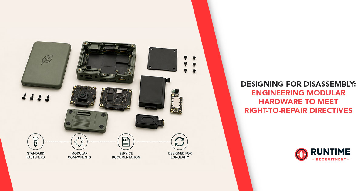
1. The Regulatory Imperative and the End of Monolithic Hardware
For decades, embedded hardware design has been driven by a push toward miniaturization, functional density, and manufacturing cost reduction. This trajectory gave rise to monolithic hardware architectures characterized by surface-mount technology (SMT), structural adhesives, glob-top potting, direct chip-on-board (COB) bonding, and integrated flex-rigid assemblies. While these methods maximized mechanical compactness and reduced bill-of-materials (BOM) costs for high-volume automated production, they rendered field servicing and component-level repair virtually impossible. Products became single-use electronic artifacts: upon the failure of a single ceramic capacitor, power MOSFET, or battery cell, the entire assembly was destined for landfill or energy-intensive recycling.
Today, this paradigm is facing a major regulatory and commercial shift. Legislative frameworks across major markets are mandating that manufacturers design products with longevity, field serviceability, and end-of-life recyclability in mind. In Europe, the EU Ecodesign Directive and the EU Right to Repair Directive (Directive 2024/1799) set binding standards requiring accessible spare parts, standardized disassembly tooling, and transparent technical documentation. In the United States, state-level legislation—such as California’s Right to Repair Act (SB 244) and similar laws in New York and Minnesota—requires OEMs to provide diagnostic tools, firmware reset utilities, and replacement sub-assemblies to independent repair shops and end users under non-discriminatory terms.
For embedded systems engineers, this legislative momentum fundamentally changes the engineering brief. Compliance cannot be retrofitted via post-hoc service manuals or aftermarket adhesive solvents; it must be architected into the hardware and firmware from the earliest conceptual design phase. Design for Disassembly (DfD) has evolved from a sustainability concept into a core engineering requirement alongside Design for Manufacturability (DFM), Design for Testability (DFT), and Design for EMC (DEMC). Mastering DfD requires embedded engineers to re-evaluate mechanical fastening strategies, PCB partitioning, high-density interconnect selection, thermal management, and firmware attestation architectures.
2. Mechanical Architecture & Fastening Strategies: Re-thinking Joinery
The mechanical enclosure and structural joining methods represent the first barrier to non-destructive disassembly. Historically, assembly lines favored permanent joinery techniques such as ultrasonic plastic welding, solvent bonding, cyanoacrylate structural glues, and permanent epoxy underfills. These techniques eliminate mechanical hardware, simplify housing mold design, and provide reliable IP67/IP68 ingress protection. However, they destroy the housing or underlying PCB trace geometry during extraction.
To meet modern repairability directives, hardware architects must transition from permanent bonding to reversible joinery without sacrificing mechanical integrity or ingress protection.
2.1 Fastener Standardization and Threaded Inserts
Proprietary fastener drives—such as pentalobe or custom spanner drives—are increasingly restricted by regulatory bodies advocating for non-proprietary tooling. Engineers should standardize on ISO metric threaded fasteners with Torx or Phillips drive profiles across the chassis. Driving self-tapping screws directly into thermoplastic housings is a poor practice for repairable designs, as repeated torque cycles strip the plastic threads. Instead, design engineers should specify heat-stake brass inserts or press-fit knurled inserts within ABS/PC bosses. This allows infinite assembly and disassembly cycles with predictable torque retention.
2.2 Reversible Seals vs. Liquid Potting
In high-vibration or outdoor embedded applications, electronics are traditionally encased in polyurethane or epoxy potting compounds to prevent moisture ingress. Potting creates an un-repairable block. Modern DfD approaches replace full potting with targeted conformal coatings paired with perimeter elastomeric gaskets (EPDM, fluoroelastomers, or liquid-injected silicone seals). Enclosure mating interfaces should utilize tongue-and-groove geometry to maintain structural pressure across gasket profiles, ensuring IP67 compliance while remaining fully serviceable using standard hand tools.
2.3 Re-thinking Thermal Interface Materials (TIMs)
High-power processing nodes—such as system-on-chips (SoCs) and field-programmable gate arrays (FPGAs)—generate substantial heat flux requiring thermal coupling to metal enclosures or heatsinks. Thermally conductive epoxy adhesives bond components permanently, turning processor replacement into a destructive operation. Modern modular designs employ non-curing phase-change materials (PCMs), high-performance silicone/graphite gap-filler pads, or compressible liquid thermal gap fillers. These materials maintain low thermal resistance while allowing effortless separation of thermal spreaders without applying mechanical stress to BGA solder balls or copper pads.
3. Interconnect Systems and PCB Partitioning for Modular Servicing
Achieving modularity requires careful partitioning of the printed circuit board assembly (PCBA). In conventional designs, a single large motherboard houses the microcontroller, power management ICs (PMICs), wireless front-ends, sensing suites, and I/O connectors. While a single board eliminates connector costs and simplifies inventory, any localized failure—such as a blown ESD protection diode on a USB transceiver—requires replacing the entire mainboard.
Modular partitioning splits the system into logical, domain-specific functional blocks:
3.1 Sub-assembly Segmentation Strategy
A robust modular taxonomy separates high-wear, high-voltage, or high-risk sub-assemblies from core compute assets. Typical functional domains include:
Core Compute Module: SoC, DRAM, eMMC/NVMe storage, PMIC, and security enclave (often realized via a standardized System-on-Module or SMARC form factor).
Power Delivery & Protection Board: AC/DC rectification, buck/boost converters, battery charging management, and transient voltage suppression (TVS).
I/O and Interface Daughterboards: Physical connectors (USB-C, RJ45, RS-485, CAN transceivers) subject to mechanical strain and field abuse.
Human-Machine Interface (HMI): Displays, capacitive touch controllers, LEDs, and haptic actuators.
3.2 High-Reliability Interconnect Selection
Connecting partitioned PCBAs demands careful evaluation of board-to-board (B2B) connectors, flexible printed circuits (FPCs), and wire harnesses.
Mezzanine Connectors: High-density, fine-pitch (0.4mm to 0.8mm) mezzanine connectors provide dense signal routing for high-speed differential pairs. Designers must select connectors rated for high mating cycles with gold-plated contacts and retention latches to resist industrial vibration.
Zero Insertion Force (ZIF) Connectors: FPC cables connecting HMIs or sensor sub-assemblies should utilize flip-lock or slide-lock ZIF connectors rather than soldered wire-to-board terminations.
Spring-Loaded Pogo Pins: For modular sensors or swappable batteries, gold-plated pogo pin arrays pressing against immersion-gold PCB landing pads offer exceptional mechanical durability and zero-tool replacement capabilities.
3.3 Signal Integrity and EMC in Modular Architectures
Routing high-speed interfaces—such as PCIe, USB4, MIPI CSI-2, or gigabit Ethernet—across physical connector interfaces introduces impedance discontinuities and parasitic inductance. Signal integrity engineers must enforce strict layout guidelines:
Impedance Matching: Maintain tight control of differential impedance (e.g., 90 Ω for USB, 100 Ω for PCIe) up to the connector pads. Specify connector pinout assignments where differential signal pairs are interleaved with dedicated ground return pins (G-S-S-G configuration) to minimize crosstalk.
Edge Rate Control and Filtering: Modular wiring harnesses can act as efficient patch antennas for EMI. Place common-mode chokes and ferrite beads immediately adjacent to connector interfaces on all off-board lines.
Localized Shielding Cans: Instead of potting the entire PCBA, use snap-on, removable board-level metal shielding cans over RF front-ends and sensitive analog chains, allowing rework while maintaining compliance with FCC/CE radiated emission limits.
4. Firmware Architecture and the "Part Pairing" Dilemma
Hardware repairability is fundamentally constrained if system firmware refuses to execute when hardware components are replaced. The rising prevalence of cryptographic "part pairing"—wherein a microcontroller's secure boot process validates the unique hardware serial number, cryptographic hash, or digital certificate of every peripheral attached to the bus—has become a major point of contention in Right-to-Repair legislation.
If an independent technician installs an OEM-genuine replacement display, battery, or camera module, but the host MCU locks the device due to an unmatched cryptographic identifier, the hardware remains effectively bricked. Embedded firmware engineers must design architectures that reconcile robust security with component swappability.
4.1 Decoupling Secure Boot from Peripheral Attestation
Secure boot must remain uncompromising in verifying the cryptographically signed bootloader, operating system, and application code running on the primary host MCU/SoC. However, peripheral attestation should not be used to enforce anti-competitive vendor lock-in.
Hardware Root of Trust (RoT): Devices utilizing secure elements (e.g., TPM 2.0 or integrated ARM TrustZone) should store peripheral configuration profiles in secure non-volatile memory (NVM) that can be field-updated via authorized diagnostic commands.
Public Key Cryptography for Peripheral Replacement: Rather than hardcoding fixed chip IDs into immutable OTP fuses, systems should implement a public-key infrastructure (PKI) model. A replacement component signed by the OEM’s intermediate certificate authority can be automatically recognized and provisioned by the host firmware during initial boot-up.
4.2 Open and Standardized Field Diagnostics
Right-to-Repair mandates require OEMs to grant independent repairers access to diagnostic software. Embedded engineers should implement industry-standard diagnostic stacks directly within system firmware:
Unified Diagnostic Services (UDS / ISO 14229): Originally developed for automotive ECUs, UDS over CAN, UART, or USB provides a standardized protocol for reading diagnostic trouble codes (DTCs), executing peripheral self-tests, re-flashing individual sub-assembly firmware, and performing sensor recalibrations.
Field Calibration Utilities: When dynamic sensors or displays are replaced, their factory calibration parameters differ from the original units. Firmware must include automated self-calibration routines or expose open API endpoints over standard interfaces (USB CDC, BLE, or WebUSB) so technicians can execute calibrations without proprietary vendor software.
4.3 Dynamic Hardware Abstraction Layers (HAL) and Bus Enumeration
Component obsolescence and supply chain disruptions often force modular systems to accept alternative component revisions over a product’s lifecycle. Embedded software architects should construct dynamic Hardware Abstraction Layers (HAL). By utilizing bus-enumeration protocols (I2C/SPI identification registers, USB descriptor tables, or PCIe capabilities lists), the driver layer can detect component variants dynamically at boot and load the corresponding driver profile without requiring complete firmware recompilation.
5. Design Trade-offs: Reliability, Form Factor, Cost, and Sustainability
Engineering modular, repairable hardware involves explicit design trade-offs. Hardware teams must balance environmental sustainability and regulatory compliance against manufacturing economics, physical footprint, and operational reliability.
5.1 Bill of Materials (BOM) vs. Lifecycle Economics
Adding connectors, daughterboards, threaded inserts, and removable enclosures increases raw BOM costs by 10% to 20% compared to monolithic designs. However, this upfront investment alters the Total Cost of Ownership (TCO). For industrial and commercial products, modularity drastically reduces warranty fulfillment costs, field maintenance expenses, and e-waste handling fees.
5.2 Reliability in Harsh Environments
Physical connectors and mechanical fasteners introduce potential points of failure under shock, thermal cycling, and humidity exposure. Gold-plated connector interfaces, anti-vibration screw locking elements (such as nylon patch screws), and environmental sealing gaskets must undergo rigorous Accelerated Life Testing (ALT) and HALT protocols. Engineers must validate that modular interfaces maintain contact resistance specifications across thousands of operational hours.
5.3 Volumetric Efficiency
Monolithic packaging yields the absolute minimum physical volume. Transitioning to modular blocks requires accepting slight increases in stack height and volumetric footprint. Through precise 3D CAD mechanical integration and ultra-fine-pitch high-speed mezzanine connectors, this spatial penalty can be kept under 15%, offering an optimal compromise between compact industrial design and modular serviceability.
6. Strategic Engineering Framework and Conclusion
Designing for disassembly is no longer an optional sustainability talking point—it is a mandatory discipline reshaping embedded systems engineering. By integrating reversible mechanical joinery, intelligent PCB sub-assembly partitioning, EMI-conscious high-speed interconnects, and open, secure firmware architectures, engineering teams can create products that comply with stringent global Right-to-Repair directives while elevating product quality and field reliability.
As regulatory frameworks tighten worldwide, embedded hardware and firmware engineers who master modular design principles will drive the next generation of sustainable, high-performance electronic products.
Connecting with RunTime Recruitment
Navigating the evolving landscape of embedded engineering, modular hardware design, and regulatory compliance requires elite technical talent. Whether you are scaling an engineering team to build next-generation repairable hardware or seeking your next technical leadership role in embedded systems, RunTime Recruitment connects industry-leading engineering firms with top-tier embedded software, hardware, and firmware professionals. Reach out to RunTime Recruitment today to supercharge your engineering capabilities.